Fontana Wall-Mounted Faucet Planning
Coordinate Faucet Height, Reach and Basin Clearance
Plan the rough-in relationship between the wall-mounted spout, finished wall, basin rim, drain and usable handwashing area.
Faucet Installation
Touchless Wall Mount
Shower Coordination
Mixer Coordination
Project Files
All Guides
Frequently Asked Questions
Is there one universal wall-mounted faucet height?
No. The correct rough-in depends on the selected faucet, spout reach, basin geometry, finished wall build-up and applicable accessibility requirements. VIEW FAUCET INSTALLATION HUB
Where should the water stream land in the basin?
Coordinate the spout projection so the stream reaches a usable washing area near the drain without striking the rim or causing excessive splash.
Why must finished-wall thickness be known early?
The valve and spout rough-in are referenced to the final surface; tile, stone, backing and waterproofing can change the usable installation depth.
What should be mocked up before final rough-in?
Confirm the faucet centerline, spout outlet, basin rim, drain location and normal hand position using the actual dimensions of the specified fixtures.
Fontana Wall-Mounted Faucets™ | Architectural and Engineering Resource
Fontana FS8014ORB Oil Rubbed Bronze Wall-Mounted Faucet:
Installation Height and Clearance Guide
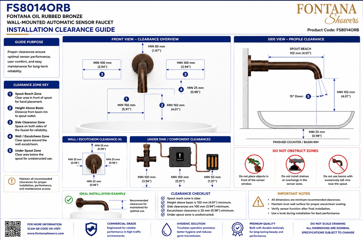
This installation-height and clearance resource is intended to support
architects, plumbing engineers, accessibility consultants, interior designers,
contractors, installers and facility managers coordinating the Fontana
FS8014ORB oil rubbed bronze wall-mounted faucet with different lavatory
applications. The guide presents recommended mounting relationships for
standard commercial restrooms, accessible restrooms, children’s restrooms,
healthcare installations, vessel basins and recessed basins. Each application
should coordinate the spout outlet above finished floor, outlet clearance
above the basin rim, countertop clearance, wall-to-basin relationship, basin
capture area, and applicable knee and toe-clearance requirements.
Fontana Oil Rubbed Bronze Wall-Mounted Faucet
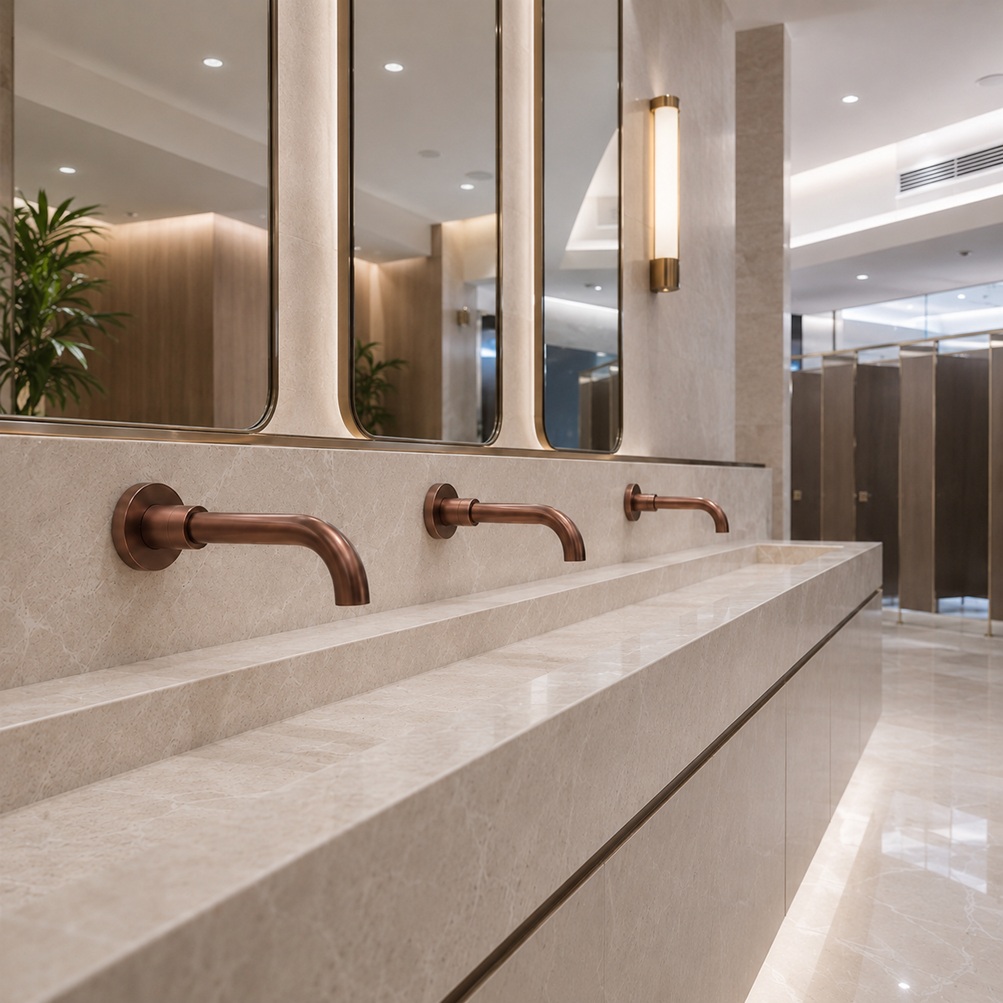
The Fontana FS8014ORB is a solid-brass wall-mounted faucet with an
oil rubbed bronze finish and a projecting curved spout. Because the
faucet is mounted independently of the countertop or lavatory, its
installation height must be coordinated with the selected basin type,
countertop elevation, finished-wall construction, user population and
accessibility requirements. Final positioning should support comfortable
handwashing while maintaining reliable water capture and sufficient
clearance for the intended application.
-
Model:
FS8014ORB
-
Installation:
Wall mounted
-
Finish:
Oil rubbed bronze
-
Material:
Solid brass
-
Fixture type:
Wall-mounted faucet spout
-
Standard spout reach:
Approximately 175 mm (6-7/8"), as illustrated
-
Children’s spout reach:
Approximately 140 mm (5-1/2"), where applicable
-
Wall relationship:
Coordinate with basin and countertop setback
-
Outlet height:
Application-specific
-
Rim clearance:
Coordinate with selected basin profile
-
Accessibility:
Knee and toe space coordination required where applicable
-
Application:
Commercial, accessible, healthcare and specialty lavatories
Required Installation Height and Clearance Drawing Package
Each installation-height drawing should use a consistent scale, dimension
style, centerline convention and product-identification block. Vertical
dimensions should be referenced from the finished floor unless another
datum is clearly identified. The faucet centerline should be coordinated
with the basin centerline, while outlet height, rim clearance, countertop
clearance and wall-to-basin dimensions should be verified against the
selected lavatory. Accessible applications should additionally identify
the required knee and toe-clearance envelope beneath the fixture.
Complete Installation Height and Clearance Guide
Shows recommended mounting relationships for standard commercial,
accessible, children’s, healthcare, vessel-basin and recessed-basin
applications. Each detail should identify the spout outlet above
finished floor, spout outlet above the basin rim, spout reach,
countertop clearance, wall-to-basin relationship and applicable
knee-clearance requirements.
Standard Commercial Restroom
Shows a typical commercial lavatory installation with the faucet
centered over the basin. The illustrated recommendation places the
spout outlet approximately 1065 mm (42 inches) above finished floor
and approximately 175–230 mm (7–9 inches) above the basin rim.
A nominal spout reach of approximately 175 mm (6-7/8 inches) and
minimum countertop clearance of approximately 38 mm
(1-1/2 inches) are indicated for coordination.
Accessible Restroom
Illustrates a wall-mounted faucet coordinated with an accessible
lavatory. The spout outlet should remain within the applicable
reach and mounting-height requirements, with the illustrated guide
showing a maximum outlet height of approximately 1015 mm
(40 inches) above finished floor. The basin, countertop and
concealed components should preserve the required knee and toe
clearance, including a nominal 685 mm (27-inch) knee-clearance
reference where applicable.
Children’s Restroom
Shows a reduced mounting height and shorter reach appropriate for
younger users. The illustrated recommendation places the spout
outlet approximately 775 mm (30-1/2 inches) above finished floor
and approximately 125–180 mm (5–7 inches) above the basin rim.
A reduced spout reach of approximately 140 mm (5-1/2 inches) may
be coordinated with a countertop height of approximately
760–815 mm (30–32 inches).
Healthcare Installation
Illustrates an elevated and service-conscious arrangement for
clinical or institutional handwashing. The guide indicates a
spout-outlet height of approximately 1120 mm (44 inches) above
finished floor and approximately 200–250 mm (8–10 inches) above
the basin rim. Adequate clearance should be maintained for
handwashing technique, cleaning and accessible knee space where
the lavatory is designed for a seated approach.
Vessel Basin
Shows the faucet coordinated with an above-counter vessel basin.
The complete height of the vessel should be included when
establishing the wall rough-in. The illustrated recommendation
places the spout outlet approximately 1065 mm (42 inches) above
finished floor and approximately 200–250 mm (8–10 inches) above
the vessel rim, with approximately 50 mm (2 inches) of minimum
countertop or wall clearance where required.
Recessed or Undermount Basin
Shows a recessed or undermount lavatory positioned below the
countertop surface. The illustrated recommendation places the
spout outlet approximately 1065 mm (42 inches) above finished
floor and approximately 150–200 mm (6–8 inches) above the basin
rim. The lower basin profile may require careful coordination of
the water landing point and approximately 32 mm (1-1/4 inches)
of minimum countertop clearance.
Wall-to-Basin Relationship
Defines the horizontal setback between the finished wall and the
selected basin. The illustrated guide indicates a typical wall
relationship ranging from approximately 64–152 mm
(2-1/2–6 inches), depending on basin construction and countertop
configuration. The faucet projection should place the water stream
within the basin capture area without striking the rear inner wall.
Knee and Toe-Clearance Coordination
Documents the clear space beneath accessible and healthcare
lavatories. Faucet connections, valve kits, supply lines, drains
and access panels should be arranged outside the required knee
and toe-clearance envelope or protected where permitted. Final
clearances should be coordinated with the selected lavatory and
the accessibility standard adopted for the project.
Engineering note:
The heights and clearances shown are planning recommendations rather
than universal installation requirements. Final mounting dimensions
should be coordinated with the actual faucet, lavatory, countertop,
user population, finished-floor elevation, wall construction, concealed
valve kit, accessibility criteria and locally adopted plumbing and
building codes. Do not scale dimensions directly from the illustration.
Architectural, Plumbing and Accessibility Coordination Considerations
Finished-Floor Datum
Establish all vertical faucet heights from the final finished-floor
elevation rather than the structural slab or unfinished substrate.
Account for floor tile, setting materials and other finish build-up.
Basin-Rim Clearance
Maintain sufficient clearance between the spout outlet and basin
rim for comfortable hand access while avoiding excessive height
that could increase splashback or reduce water capture.
Wall-to-Basin Setback
Coordinate the finished-wall plane, countertop depth and basin
position with the faucet reach so the outlet remains centered
over the intended handwashing and water-capture area.
Accessible Knee Space
Keep piping, valve kits, control components and access panels
outside the required knee and toe-clearance envelope. Protect
exposed supply and drain components where required.
User Population
Adjust mounting height and reach for the intended occupants,
including children, seated users, healthcare staff and other
specialized applications, rather than applying one height to
every installation.
Water Capture and Splash Control
Confirm the actual water landing point after installation and
ensure it remains within the basin capture area without striking
the rear wall, passing over the front rim or creating excessive
splashback.
FontanaShowers Installation and Specification Resources
FS8014ORB Product Page
Product information, oil rubbed bronze finish details,
technical specifications and available documentation for the
Fontana FS8014ORB wall-mounted faucet.
FontanaShowers Installation Hub
Central installation information for wall-mounted faucets,
automatic faucets, concealed connections and related
FontanaShowers fixtures.
FS8014ORB Dimensional Coordination
Review current faucet dimensions, spout projection and available
technical documentation before setting final wall-mounting heights.
Wall-Mounted Faucet Installation Guidance
General guidance covering wall preparation, mounting elevations,
basin coordination, concealed connections, sealing and testing.
Product Submittal Verification
Confirm current dimensions, mounting requirements, connection
information and product limitations before releasing coordinated
construction documents.
Fixture Testing and Commissioning
General installation resources covering supply flushing,
water-stream verification, leak testing, cleaning and final
fixture commissioning.
Professional Engineering and Accessibility References
-
U.S. Access Board – Plumbing Elements and Facilities
Provides federal accessibility guidance for lavatories, sinks,
faucets, knee clearance, toe clearance and accessible restroom
elements.
-
U.S. Access Board – Lavatories and Sinks Guide
Explains accessible lavatory height, approach, clear floor space,
knee and toe clearance, reach ranges and fixture coordination.
-
International Code Council – Building and Accessibility Codes
Provides model-code resources relevant to accessible plumbing
fixtures, lavatory clearances and restroom planning requirements.
-
EPA WaterSense – Bathroom Faucets
Provides information concerning water-efficient bathroom faucets,
performance criteria and water-conservation considerations.
-
OSHA – Restroom and Sanitation Requirements
Summarizes workplace requirements for sanitary restrooms and
readily accessible handwashing facilities.
Project verification:
Installation-height and clearance guides are coordination tools and do
not replace approved project submittals or project-specific accessibility
review. The architect, plumbing engineer, accessibility consultant,
interior designer, contractor and licensed installer should verify the
spout outlet above finished floor, outlet clearance above the basin rim,
countertop clearance, wall-to-basin relationship, basin centerline,
water landing point, knee and toe clearance, concealed component location,
user requirements and locally adopted codes before installation.
|
|
|