Complete System Reliability
From Sensor to Solenoid: Why Touchless Faucet Reliability Is More Than the Sensor
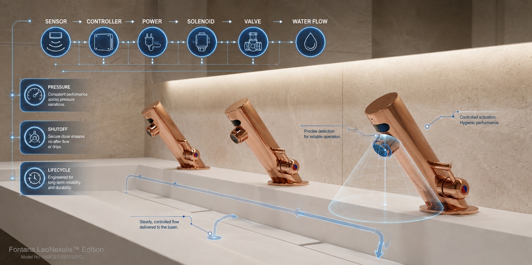
A sensor can make the correct detection decision and the faucet can still fail. Commercial reliability depends on the entire operating chain—from sensing and controller logic through electrical power, solenoid actuation, valve sealing and hydraulic performance.
The sensor only starts the process
When a user places their hands beneath a touchless faucet, the sensor's job is to determine whether an intended target is present.
But detection alone does not produce water.
The controller must interpret the sensor data, the electrical system must provide usable power, the solenoid must actuate, the valve must open correctly, water must flow through the hydraulic path, and the entire sequence must reverse correctly when the user's hands leave.
System Engineering
“Sensor failure” is often an incomplete diagnosis
A faucet that fails to activate, stays on, closes slowly, leaks or produces inconsistent flow may have a sensing problem—but it may also have an electrical, controller, solenoid, valve, filter, pressure or hydraulic problem.
Reliability Principle
Reliability is the probability that the complete chain performs correctly
A commercial faucet succeeds only when every required subsystem performs its role at the right time.
Good sensor performance cannot compensate for an unreliable valve. A durable valve cannot compensate for unstable power. Strong electronics cannot compensate for poor detection geometry.
Operating Chain
What Happens Between Hand Detection and Water Flow?
|
Observed Symptom
|
Possible Sensor / Control Cause
|
Possible Mechanical / Hydraulic Cause
|
|
Observed Symptom: No water
|
Possible Sensor / Control Cause: Missed detection, controller or power problem
|
Possible Mechanical / Hydraulic Cause: Closed supply, blocked filter or solenoid/valve fault
|
|
Observed Symptom: Intermittent activation
|
Possible Sensor / Control Cause: Detection geometry, electrical connection or power instability
|
Possible Mechanical / Hydraulic Cause: Intermittent valve or supply condition
|
|
Observed Symptom: Faucet stays on
|
Possible Sensor / Control Cause: Sensor continues classifying a target as present
|
Possible Mechanical / Hydraulic Cause: Valve or solenoid fails to close completely
|
|
Observed Symptom: Slow shutoff
|
Possible Sensor / Control Cause: Control timing or target-exit logic
|
Possible Mechanical / Hydraulic Cause: Solenoid/valve response delay
|
|
Observed Symptom: Dripping after shutoff
|
Possible Sensor / Control Cause: Usually not primarily sensor related
|
Possible Mechanical / Hydraulic Cause: Debris, seal or valve closure issue
|
|
Observed Symptom: Low flow
|
Possible Sensor / Control Cause: Usually not a sensing issue
|
Possible Mechanical / Hydraulic Cause: Filter, regulator, aerator, pressure or supply restriction
|
|
Observed Symptom: Unexpected activation
|
Possible Sensor / Control Cause: False target classification or excessive detection zone
|
Possible Mechanical / Hydraulic Cause: Not normally hydraulic unless water remains flowing after a valid command ends
|
Diagnostic Principle
Do not diagnose the sensor merely because the faucet is automatic. Diagnose the point in the operating chain where commanded behavior and actual behavior separate.
Subsystem 01
Sensor: Was the intended target detected correctly?
For a ToF implementation, the sensor provides target-distance information that can be used to determine whether hands fall inside the intended activation range.
The relevant reliability questions include repeatable range measurement, detection angle, false-positive behavior, false-negative behavior, optical stability and neighboring-fixture interaction.
The detailed sensing layer is covered in
detection-zone control and short-range sensing geometry.
Subsystem 02
Controller: Was the sensor information interpreted correctly?
The sensor provides information. Firmware determines what that information means.
The controller may apply distance thresholds, filtering, timing, hysteresis, confidence logic, automatic shutoff rules and fault handling before deciding whether the solenoid should be energized.
That means two faucets using similar sensor technology can behave differently because the complete control implementation is different.
Subsystem 03
Power: Can the system execute the command reliably?
Sensor and controller behavior depend on stable electrical power.
Battery voltage, low-voltage supply quality, transformers, wiring, connectors and power-failure behavior can all influence system operation.
A complete reliability test should therefore verify not only normal operation but also the faucet's safe state when voltage becomes abnormal or power is lost.
Subsystem 04
Solenoid: The bridge between electronics and water
The solenoid converts an electrical command into mechanical valve movement.
If the controller sends the correct command but the solenoid does not actuate fully, does not release correctly, responds slowly or becomes affected by debris or wear, the user experiences a faucet failure even though the sensing decision was correct.
The solenoid is therefore not an accessory to the sensor system. It is one of the primary reliability components.
Subsystem 05
Valve: Opening is only half the reliability problem
A reliable valve must open when commanded, provide the intended flow path and then close completely when commanded off.
Sealing surfaces, diaphragms, springs, moving elements and contamination can all influence long-term performance.
This is why post-cycle sealing checks matter. Reaching a lifecycle count means little if the faucet no longer closes correctly afterward.
Subsystem 06
Hydraulics: The plumbing system determines the load
Supply pressure, flow restriction, water quality, inlet filtration, outlet restriction and transient pressure conditions all affect the valve system.
A faucet may detect perfectly while delivering inadequate flow because of a blocked filter or low supply pressure.
Conversely, excessive pressure or hydraulic shock can stress mechanical components even though the electronics continue functioning normally.
The test procedure follows the same system-level logic
10–30 cm
Sensing-distance criterion; 12 cm preset
<30°
Sensing-angle criterion
IP67
PCB/electronics waterproofing criterion
200,000
Lifecycle activation cycles with post-cycle checks
The broader procedure also addresses sensing behavior, interference, response timing, power-failure behavior, environmental exposure, hydraulic pressure and lifecycle performance. That is important because these are
finished-faucet criteria, not isolated sensor-chip testing.
Scope note: the documented values should be described as Fontana finished-product inspection criteria and not as isolated qualification results for the ToF semiconductor.
|
Test Family
|
Primary Subsystem
|
System Question
|
|
Test Family: Sensing range / angle
|
Primary Subsystem: Sensor + controller
|
System Question: Is the intended target recognized in the correct zone?
|
|
Test Family: Anti-interference
|
Primary Subsystem: Sensor + firmware
|
System Question: Does the system reject irrelevant environmental input?
|
|
Test Family: Opening / closing timing
|
Primary Subsystem: Controller + power + solenoid + valve
|
System Question: Does the complete chain respond within acceptable time?
|
|
Test Family: Power-failure state
|
Primary Subsystem: Power + controller + solenoid
|
System Question: Does the valve remain or become safely closed?
|
|
Test Family: Waterproofing / humidity
|
Primary Subsystem: Electronics + enclosure
|
System Question: Does the electronic system survive the restroom environment?
|
|
Test Family: Pressure testing
|
Primary Subsystem: Valve + hydraulic path
|
System Question: Can mechanical components withstand plumbing-system loads?
|
|
Test Family: Lifecycle cycling
|
Primary Subsystem: Complete faucet
|
System Question: Does repeated operation degrade sensing, actuation, flow or sealing?
|
Field Validation
Eight Years of ToF Deployment Has Tested More Than the Sensor
Fontana’s ToF architecture has been implemented for approximately eight years across hundreds upon hundreds of commercial projects.
Those installations have not exposed only the sensor to real operating conditions. They have exposed the complete system—the controller, electrical supply, wiring, solenoid, valve, filters, plumbing connections and hydraulic path.
That is why project history is system-reliability evidence, not merely sensor field history.
~8 Years
Commercial ToF implementation
Hundreds
upon hundreds of commercial projects
Complete
sensor-to-valve operating chain
Real Field
plumbing and operating conditions
Real-World Exposure
What Project History Exposes the Complete System To
Different Basins
Different sensing and outlet geometries.
Different Pressures
Different loads on valves and flow components.
Water Quality
Real debris, mineral content and filtration conditions.
Electrical Conditions
Battery and mains-powered installation differences.
High Usage
Repeated real-world activation and valve cycles.
Cleaning
Moisture, chemical exposure and routine facility activity.
Installation Variation
Real differences in wiring, plumbing and mechanical fit.
Maintenance
Actual service events and component replacement history.
True False Activation
The sensing/control system incorrectly determines that an intended target is still present and continues commanding water flow.
Valve Closure Failure
The sensing/control system correctly commands OFF, but the solenoid or valve does not fully stop the hydraulic flow.
System Timing
Sensor response time is not water-at-outlet response time
A sensor may calculate target distance extremely quickly, but the user's experience includes the complete time required for classification, control logic, electrical actuation, solenoid movement, valve opening and hydraulic flow.
For specification purposes, complete faucet opening and closing behavior is therefore more meaningful than quoting semiconductor processing speed by itself.
Lifecycle Engineering
What a 200,000-Cycle Test Should Actually Tell You
The useful question is not simply whether a test rig reached 200,000 activations.
Does sensing remain stable?
Verify detection after cycling.
Does the solenoid still actuate?
Mechanical response must remain consistent.
Does the valve seal?
Post-cycle leakage matters.
Does flow remain acceptable?
Hydraulic performance must remain functional.
|
Factory Validation
|
Commercial Field Validation
|
|
Factory Validation: Known test conditions
|
Commercial Field Validation: Real installation variation
|
|
Factory Validation: Defined pressure tests
|
Commercial Field Validation: Different building pressure conditions
|
|
Factory Validation: Controlled environmental exposure
|
Commercial Field Validation: Years of actual restroom exposure
|
|
Factory Validation: Accelerated cycle testing
|
Commercial Field Validation: Calendar-time operation and real maintenance
|
|
Factory Validation: Repeatable failure investigation
|
Commercial Field Validation: Unexpected combinations of real conditions
|
Strong reliability evidence comes from controlled finished-product testing plus sustained field operation of the complete system.
Architecture Changes
Changing the sensor architecture means revalidating the system around it
Replacing an established ToF implementation with an emerging faucet-sensing architecture such as mmWave is not merely a sensor substitution.
mmWave radar is a highly capable and mature sensing technology in applications such as automotive systems, occupancy detection and industrial sensing. Its use as the primary activation architecture in commercial touchless faucets, however, remains comparatively emerging and does not yet have the same broad faucet-specific deployment history as conventional IR or established ToF implementations.
The architecture change can affect controller firmware, electrical power, packaging, physical geometry, antenna or optical behavior, interference management, actuation timing and ultimately the interaction between sensing decisions and valve commands.
This is why
a proposed mmWave replacement should be evaluated as a complete faucet architecture,
not merely as a radar-module demonstration.
Sensor Maturity and Faucet-System Maturity Are Different
A sensing technology can be highly mature at the semiconductor or module level without having an equally mature commercial-faucet implementation. Faucet maturity requires proven packaging, power architecture, controller integration, environmental protection, valve coordination, manufacturing control, commissioning procedures, serviceability and field operation.
That distinction is particularly important when comparing Fontana’s approximately eight years of ToF commercial implementation with an alternative sensing architecture that may have strong technical capability but substantially less faucet-specific field history.
Specification Review
What Engineers Should Review Beyond the Sensor
Sensor Architecture
What is measured and how is the zone defined?
Application Maturity
What commercial faucet deployment and validation history exists?
Controller Logic
How are targets classified and faults handled?
Power Source
Battery, mains or hybrid architecture and fail-safe state.
Solenoid
Actuation speed, replacement and service access.
Valve
Opening, closure, sealing and pressure behavior.
Hydraulics
Pressure limits, flow regulation and filtration.
Lifecycle Testing
How is the complete faucet evaluated after cycling?
Field Record
What long-duration commercial implementation exists?
System Performance Conclusions
Touchless Faucet Reliability Must Be Evaluated End to End
The sensor determines whether an intended target is present. It does not independently determine whether water reaches the user, whether the valve closes, whether the faucet seals under pressure or whether the system remains stable after years of operation.
Fontana’s finished-product validation therefore addresses sensing, electrical, environmental, hydraulic and lifecycle behavior, while approximately eight years of ToF implementation across hundreds upon hundreds of commercial projects adds a separate layer of real-world system exposure.
The same standard must apply when a different sensing architecture is proposed. An emerging radar-based faucet architecture should be evaluated not only for its ability to detect a target, but for how successfully it integrates with the controller, power system, solenoid, valve, hydraulics and lifecycle requirements of the finished fixture.
The correct reliability question is not “Which sensor does this faucet use?” It is “How reliably does the entire system convert an intended user interaction into controlled water flow—and then shut that flow off correctly?”
Continue the Sensor Engineering Series
Return to the primary sensor comparison or examine the specialist topics that feed into complete system reliability.
Technical References
STMicroelectronics:
Direct Time-of-Flight proximity and ranging technology.
Texas Instruments:
IWRL6432WMOD 60 GHz mmWave sensing module.
Fontana finished-product evidence referenced in this engineering series includes factory inspection procedure V3.0 dated May 15, 2026, addressing sensing, electrical, environmental, hydraulic and lifecycle acceptance criteria.
Fontana field evidence referenced on this page includes approximately eight years of ToF implementation across hundreds upon hundreds of commercial projects.
|
|
|











