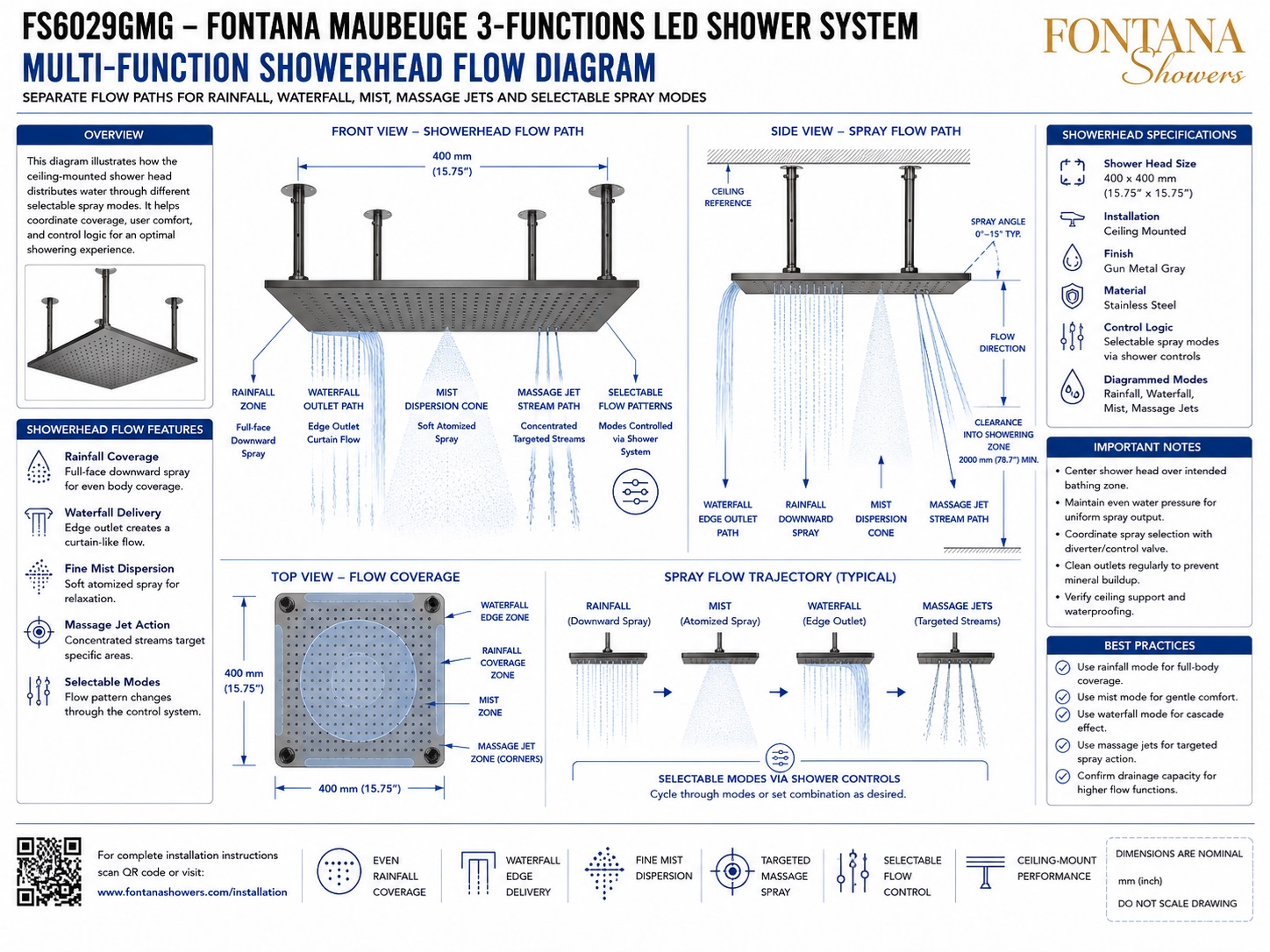
Large Rain Shower Systems Flow Chart
Multi-Function Showerhead
A multi-function showerhead flow diagram documents how tempered water is controlled and distributed to each selectable spray function. It connects the mixing valve, selector controls, internal waterways, manifolds and terminal outlets in one coordinated hydraulic sequence.
Read More
Large-format systems may include rainfall, waterfall, mist, massage jets, hand-shower delivery, rain-curtain effects and approved mixed modes. Because function count, inlet arrangement, valve logic and permitted operating combinations vary by model, the final diagram should follow the approved product submittal rather than a generic plumbing symbol.
Architects, plumbing engineers, BIM coordinators, specifiers, contractors and commissioning teams can use the flow diagram to coordinate preliminary layouts, rough-ins, performance expectations and long-term service access.
Plotting the Main Flow Path
Begin with the hot- and cold-water supplies entering a thermostatic or pressure-compensating mixing valve. Tempered water then moves to the selector diverter or valve bank, where each port is identified by its destination.
- Use directional arrows to establish the complete water-flow sequence.
- Label rainfall, waterfall, mist, massage-jet and hand-shower circuits clearly.
- Document pipe sizes, connection standards, isolation points and service access.
- State every approved single-function and simultaneous operating combination.
Read More
- Rainfall, waterfall and mist functions may require separate internal waterways.
- Rainfall typically uses a distributed field of overhead nozzles.
- Waterfall delivery generally discharges through a linear slot or blade opening.
- Mist outlets may require additional filtration, cleaning access and water-quality coordination.
- Massage jets may use a dedicated manifold with multiple directional outlets.
- Identify separate circuits with line types, circuit numbers or keyed symbols.
Recommended Multi-Function Flow Chart
Document each circuit by discharge element, required technical information and coordination purpose.
Rainfall Circuit
Show the inlet, design flow, operating pressure and active spray area for consistent overhead coverage.
Waterfall Circuit
Identify the dedicated port, flow direction and linear outlet edge for focused water delivery.
Mist Circuit
Document the separate waterway, filtration provisions and accessible service points.
Massage-Jet Circuit
Record the jet count, branch arrangement and balancing method for uniform pressure.
Hand-Shower Circuit
Coordinate the connection, hose length, holder location and dedicated control.
Mixed-Mode Operation
List approved combinations and verify the total flow demand against valve and supply capacity.
Valve Selection
Confirm that the selected valve supports the required pressure, flow and operating combinations.
Read More
The plumbing engineer should evaluate available dynamic pressure, total flow demand, elevation differences, fitting losses, branch lengths, outlet resistance and simultaneous-use expectations. Nominal connection size alone does not establish system performance.
Combined-Demand Review
A system may perform correctly in rainfall-only mode but lose coverage when waterfall and massage circuits operate together.
Applicable Shower Standards
Coordinate plumbing supply fittings and automatic compensating shower valves with the adopted code and approved product data.
Read More
ASME A112.18.1/CSA B125.1:24 covers plumbing supply fittings, including showerheads, handheld showers, body sprays and related components. Automatic compensating valves for individual showers should be reviewed under ASSE 1016/ASME A112.1016/CSA B125.16 and the requirements of the authority having jurisdiction.
Professional reference: Coordinate plumbing supply fittings, shower-valve requirements, manufacturer data and the adopted plumbing code.
BIM & Construction Document Integration
Use Consistent Circuit Identifiers
Match flow-diagram identifiers with plumbing plans, valve schedules, reflected ceiling plans, elevations, BIM models and commissioning records.
Coordinate Digital Resources
Review BIM/Revit content, specification sheets, dimensional details and installation guides against the approved project submittal before construction.
Example AEC Coordination Case
A resort shower system included rainfall, waterfall, mist, six massage jets and a hand shower, but the original schematic did not define simultaneous operation.
Read More
The owner expected rainfall, waterfall and body jets to operate together, while the scheduled valve had been selected for single-function demand. This created a coordination risk for pressure, flow and temperature stability.
Engineering Revision
The system was revised with separate circuits, approved combinations, a balanced body-jet manifold and accessible isolation points.
Read More
Rainfall and waterfall branches were redirected to reduce unnecessary fittings, the mist circuit received an accessible cleaning point, and the valve and supply branches were reassessed under the combined design condition.
Clear Installation Sequence
The revised diagram gave installers a defined routing path and commissioning teams a clear test sequence for every spray function.
Reduced Concealed Rework
Early coordination helped prevent ceiling modifications after waterproofing and finish installation.
Specification and Commissioning Conditions
Complete Multi-Function Flow Documentation
A complete flow diagram supports accurate rough-ins, stable hydraulic performance, fewer RFIs and reliable long-term serviceability.
|
|
|