Diverter and Control Layout for
Large Rain Shower Head Systems
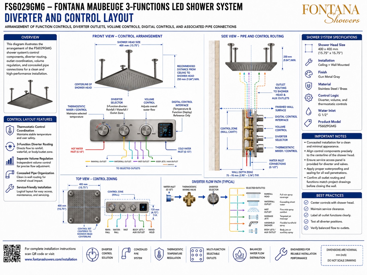
A coordinated diverter and control layout defines how users select, regulate, and combine rainfall, waterfall, hand-shower, body-jet, mist, and massage functions. It should clearly document the visible controls, concealed valves, outlet sequence, pipe connections, installation depths, and service requirements.
Read More
For architects, plumbing engineers, interior designers, BIM coordinators, contractors, and commissioning teams, the layout should communicate the complete operating strategy rather than show only the decorative trim. FontanaShowers offers manual, thermostatic, and digitally controlled systems for overhead rain showers, handheld sprays, and body jets. Product-specific valve logic, approved outlet combinations, and technical resources should be verified before construction documents are issued.
Control Layout and User Sequence
The control elevation should identify the location and purpose of every handle, button, touchscreen, or rotary selector. Temperature, outlet-selection, and volume controls should remain visually distinct for clear, intuitive operation.
- TC-1: Thermostatic temperature control
- DV-1: Three- or four-way diverter
- VC-1: Rain shower volume control
- VC-2: Hand-shower volume control
- VC-3: Body-jet volume control
- DC-1: Digital shower interface
- Coordinate identifiers across schematics, valve schedules, BIM objects, elevations, installation details, and commissioning records.
- Position controls thoughtfully in relation to user reach, shower doors, seating, grab bars, handheld fixtures, and active spray zones.
- Label diverter outlets by destination rather than by unexplained port numbers.
Read More
A diverter routes mixed water from the thermostatic or pressure-compensating valve to the selected shower functions. The drawing should state whether the valve permits one function at a time or approved simultaneous combinations. This distinction affects valve capacity, pipe sizing, available pressure, drainage demand, and user expectations. Unused ports should be handled only as directed by the manufacturer.
Volume Controls and Hydraulic Zoning
Independent volume controls regulate individual outlets without changing the selected mixed-water temperature. In larger systems, this approach can provide clearer zoning and more predictable hydraulic performance.
System Demand and Outlet Balance
Evaluate the most demanding approved operating mode using dynamic pressure, branch length, elevation, fitting losses, valve resistance, outlet resistance, and simultaneous flow.
Read More
A large rain shower may require a different operating flow from a hand shower or body-jet bank. Independent controls can help balance these functions and support simultaneous operation only when the valve assembly and supply system are designed for the combined demand.
Diverter and Control Coordination
Document each component, its required drawing information, and its AEC coordination objective.
Temperature Control
Show valve type, centerline, safety stop, and adjustment range to establish stable mixed-water control.
Diverter
Identify the inlet, every outlet, and all permitted combinations to define the function-selection logic.
Volume Control
State the controlled outlet, flow direction, and connection size to support independent regulation.
Digital Interface
Coordinate power, data, mounting height, control functions, and required access for electronic operation.
Valve Body
Document rough-in depth, structural support, port orientation, and access to prevent concealed conflicts.
Pipe Connections
Confirm sizes, thread types, routing, flow direction, and identification to reduce field errors.
Service Zone
Provide trim-removal clearance, cartridge access, shutoff access, and adequate working space.
Coordination priority: Match the control sequence, hydraulic design, rough-in dimensions, and service strategy to the approved product submittal.
Digital Shower Controls
Integrated User Control
Digital interfaces can combine temperature adjustment, outlet selection, flow management, presets, and timers in one wall-mounted control.
System Components
Show the controller, concealed processor or valve module, power source, wiring, communication cables, sensors, and service access.
Electrical Coordination
Coordinate listed electrical components with applicable codes, manufacturer instructions, waterproofing, and accessible service locations.
Read More
Transformers, drivers, processors, and connection enclosures should remain accessible. They should not be placed where routine service requires removal of permanent waterproof finishes. The specification should also distinguish water-powered displays from controls that require a building electrical supply.
Valve Standards and Temperature Safety
Coordinate plumbing supply fittings, shower controls, showerheads, handheld showers, and body sprays with the applicable product standards and adopted plumbing code.
Automatic Compensating Valves
Point-of-use shower valves should be selected and commissioned according to their listed operating limits and approved installation requirements.
Read More
Automatic compensating valves used at individual showers are addressed by ASSE 1016/ASME A112.1016/CSA B125.16. The standard applies where the user controls flow or final temperature and where additional downstream mixing does not occur.
Professional Technical References
Use the current plumbing supply-fitting standard, shower-valve requirements, product listings, and authority requirements as the basis for design and commissioning.
Illustrative AEC Coordination Case
Complete Diverter and Control Documentation
A coordinated control strategy improves hydraulic performance, simplifies commissioning, and supports reliable long-term operation.
|
|
|