Fontana FS8014ORB Installation Coordination
Review the Wall Rough-In Dimensions
Coordinate product-specific mounting depth, connection locations, finished-wall buildup and trim alignment.
Primary Guide
Valve
Ceiling
Body Jets
Hand Shower
All Guides
Frequently Asked Questions
Are these wall rough-in dimensions universal?
No. This detail is associated with FS8014ORB. Confirm the exact SKU before using its dimensions on a project.
Open Shower Installation Hub
Which wall plane governs mounting depth?
Use the completed finished-wall plane, including backing, waterproofing, tile or stone and setting materials.
When should trim alignment be checked?
Check the permitted depth and alignment during rough-in and again before permanently closing the wall.
What must be tested before enclosure?
Flush and pressure-test concealed piping and confirm that every connection and outlet matches the product diagram.
Fontana Wall-Mounted Faucets™ | Architectural and Engineering Resource
Fontana FS8014ORB Oil Rubbed Bronze Wall-Mounted Faucet:
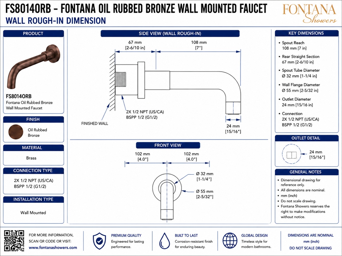
Wall Rough-In Dimensions
This wall rough-in drawing resource is intended to support architects,
plumbing engineers, interior designers, contractors, installers and facility
managers coordinating the Fontana FS8014ORB oil rubbed bronze wall-mounted
faucet before finished wall surfaces are installed. The drawing package
communicates the finished-wall reference, spout centerline, required wall
penetration, mounting-hole locations, concealed connection location,
valve-kit connection point, finished-wall thickness range, basin and
countertop references, and horizontal and vertical rough-in coordinates.
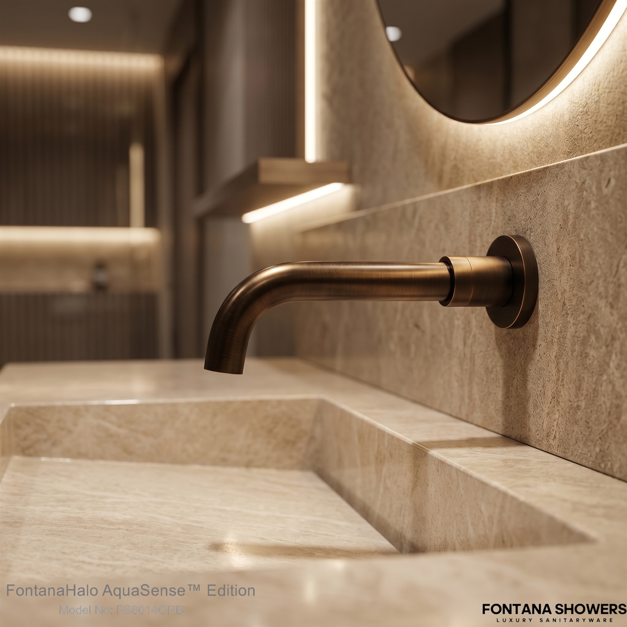
Fontana Oil Rubbed Bronze Wall-Mounted Faucet
The Fontana FS8014ORB is a solid-brass wall-mounted faucet with an
oil rubbed bronze finish and a curved projecting spout. Its concealed
wall connection keeps the countertop clear while supporting a clean
architectural installation. The rough-in drawing is used to establish
the faucet centerline, wall penetration, concealed valve-kit position
and finished-wall relationship before tile, stone, wall board or
decorative wall panels are installed.
-
Model:
FS8014ORB
-
Installation:
Wall mounted
-
Finish:
Oil rubbed bronze
-
Material:
Solid brass
-
Fixture type:
Wall-mounted faucet spout
-
Spout reach:
108 mm, as shown
-
Spout tube diameter:
Ø32 mm
-
Outlet diameter:
Ø24 mm
-
Escutcheon diameter:
Ø55 mm
-
Wall penetration:
Ø55 mm, as shown
-
Wall thickness range:
10–35 mm
-
Connection:
Coordinate with selected valve kit
Required Wall Rough-In Drawing Package
Each drawing should use a consistent scale, dimension style and product
identification block. Rough-in measurements should be referenced from the
final finished-wall plane, faucet centerline and top of the finished
countertop. The drawing should distinguish verified product dimensions
from reference dimensions that may vary according to the selected concealed
valve kit, connection fitting, wall construction and basin configuration.
Standard Wall Rough-In Drawing
Shows the complete pre-installation arrangement of the Fontana
FS8014ORB wall-mounted faucet, including the front elevation,
side elevation, finished-wall line, spout centerline, wall
penetration, concealed connection area, valve-kit location,
countertop reference and basin alignment. This drawing provides
the primary construction reference before the wall assembly is
closed or finished.
Finished-Wall Reference
Defines the final exposed wall plane from which the faucet
projection and concealed connection depth are measured. The
reference should include the complete wall build-up, such as
tile, stone, setting material, wall board and waterproofing,
rather than the face of the structural framing alone.
Spout Centerline and Rough-In Coordinates
Identifies the horizontal and vertical faucet centerline relative
to the basin and countertop. The drawing indicates a typical
centerline height of approximately 170 mm (6-11/16 inches) above
the countertop, together with horizontal reference coordinates
of 102 mm (4 inches) on each side of the centerline.
Wall Penetration and Mounting Locations
Shows the required wall penetration for the projecting spout and
identifies the mounting-hole or attachment locations associated
with the escutcheon and concealed support. The drawing indicates
a nominal Ø55 mm (2-5/32 inches) wall penetration. Final hole
locations should be transferred from the approved mounting
template or installation hardware.
Concealed Connection Location
Defines the concealed plumbing connection behind the finished
wall and its relationship to the faucet centerline. The exact
connection depth and fitting position may vary according to the
selected valve kit, wall thickness and project piping arrangement
and should therefore be confirmed before the wall is closed.
Valve-Kit Connection Point
Identifies the connection point serving the wall-mounted faucet
and the recommended service area beneath the countertop. The valve
kit should remain accessible for installation, pressure testing,
adjustment and future maintenance. Follow the instructions supplied
with the selected Fontana valve kit for final placement.
Finished-Wall Thickness Range
Shows the allowable finished-wall thickness between the concealed
connection and the visible escutcheon. The dimensional drawing
indicates a nominal wall thickness range of 10–35 mm
(3/8–1-3/8 inches). Verify that the selected wall assembly remains
within the compatible installation range.
Basin and Countertop References
Documents the relationship between the faucet centerline, top of
countertop, basin rim and usable basin area. The outlet should be
positioned so the water stream enters the basin without striking
the backsplash, countertop or front rim. Basin dimensions should
be coordinated before finalizing the vertical rough-in height.
Engineering note:
The concealed connection location and valve-kit connection point shown
on the dimensional drawing are reference positions only. Exact placement
may vary according to the selected Fontana valve kit, wall construction,
countertop thickness, basin geometry and plumbing layout. Verify all
rough-in coordinates against the approved product submittal and valve-kit
installation instructions before drilling or closing the wall.
Architectural and Plumbing Coordination Considerations
Finished-Wall Build-Up
Coordinate the total thickness of tile, stone, adhesive,
waterproofing, wall board and other finish layers so the
escutcheon seats evenly against the final finished-wall plane.
Basin Alignment
Align the faucet centerline with the basin’s usable capture area
and verify that the projecting outlet provides suitable clearance
from the backsplash, basin rim and countertop.
Mounting Support
Provide solid backing, blocking or a securely anchored concealed
connection where required so the projecting wall-mounted faucet
remains stable during operation and maintenance.
Valve-Kit Access
Locate the concealed valve kit in an accessible service area and
avoid permanently enclosing adjustment points, threaded
connections or components requiring future maintenance.
Wall Penetration
Confirm the required penetration diameter and centerline before
cutting tile, stone or wall panels. Protect surrounding
waterproofing and seal around the escutcheon where required.
Pressure Testing
Complete connection inspection and pressure testing before
closing the wall. Confirm that concealed joints remain accessible
until the installation has been tested and accepted.
FontanaShowers Installation and Specification Resources
FS8014ORB Product Page
Product information, oil rubbed bronze finish details,
technical specifications and available documentation for the
Fontana FS8014ORB wall-mounted faucet.
FontanaShowers Installation Hub
Central installation information for wall-mounted faucets,
bathroom faucets, concealed connections and other
FontanaShowers fixtures.
FS8014ORB Rough-In Coordination
Review the current product page and available technical
documentation before establishing wall penetrations,
centerlines or concealed connection locations.
Wall-Mounted Faucet Installation Guidance
General guidance for finished-wall preparation, structural
support, concealed plumbing connections, sealing, testing and
final fixture installation.
Product Submittal Verification
Confirm current product dimensions, valve-kit compatibility,
finish information and installation requirements before
releasing construction documents.
Fixture Installation Resources
General installation resources covering wall preparation,
connection inspection, pressure testing, commissioning,
cleaning and maintenance.
Professional Engineering and Accessibility References
Project verification:
Wall rough-in drawings are coordination tools and do not replace approved
project submittals. The architect, plumbing engineer, contractor and licensed
installer should verify the finished-wall plane, wall thickness, faucet
centerline, wall penetration, mounting locations, concealed connection,
valve-kit position, basin alignment, countertop elevation, structural support,
connection compatibility, accessibility requirements and locally adopted
codes before construction proceeds.
|
|
|