Installation Guide for the Durable Fontana Smart Infrared Automatic Sensor Faucet for Commercial Use | FS-549RR
|
Easy step by steps installation instructions for Sensor Faucet
|
|
Visit Product Page 
|
|
- Prior to beginning, thoroughly read through the following installation instructions. Adhere to all local construction and safety standards.
- Unbox and inspect the parts for any defects during shipping. If you find any, do not install.
- You should note that all components have to be installed by a licensed and qualified plumber, or else the warranty can be rendered null and void.
|
sensor
|

|
|
Sensor Faucet Installations Instructions
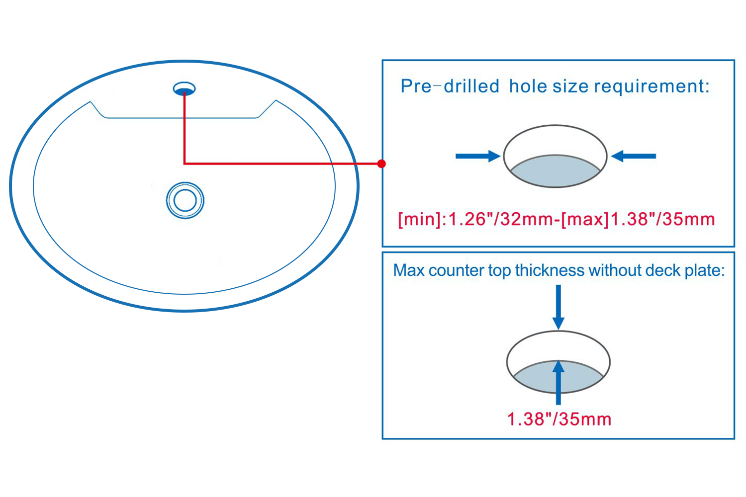
| Hole Size Chart : |
|
|
|
sensor
|
|
|
|
|
|
|
Deck Mount Installation
|
|
|
|
|
|
|
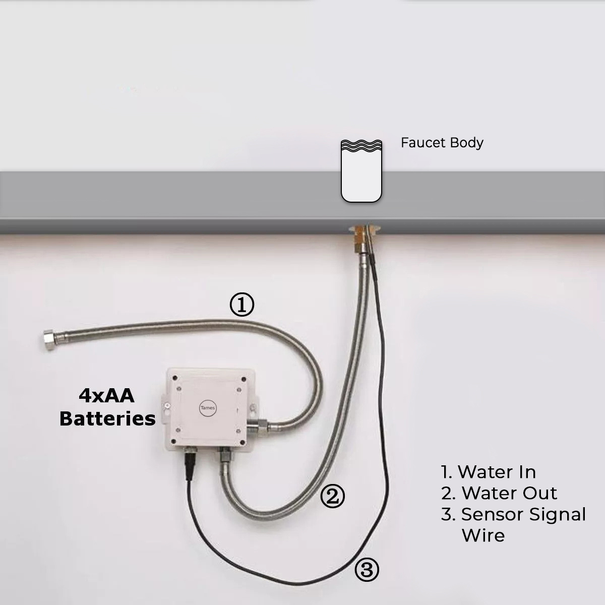
Battery (DC 6V) Only Control Box
|
|
|
|
Step 1:
|
|
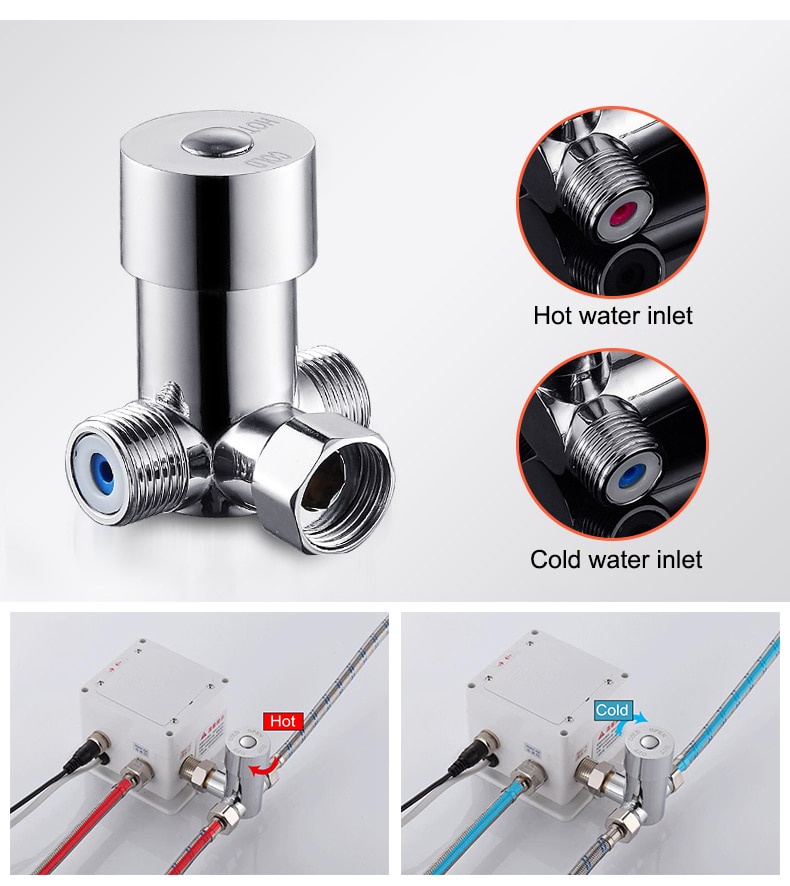
Step 2: (Hot & Cold Connection)
|
|
sensor
|

|
|
|
|
|
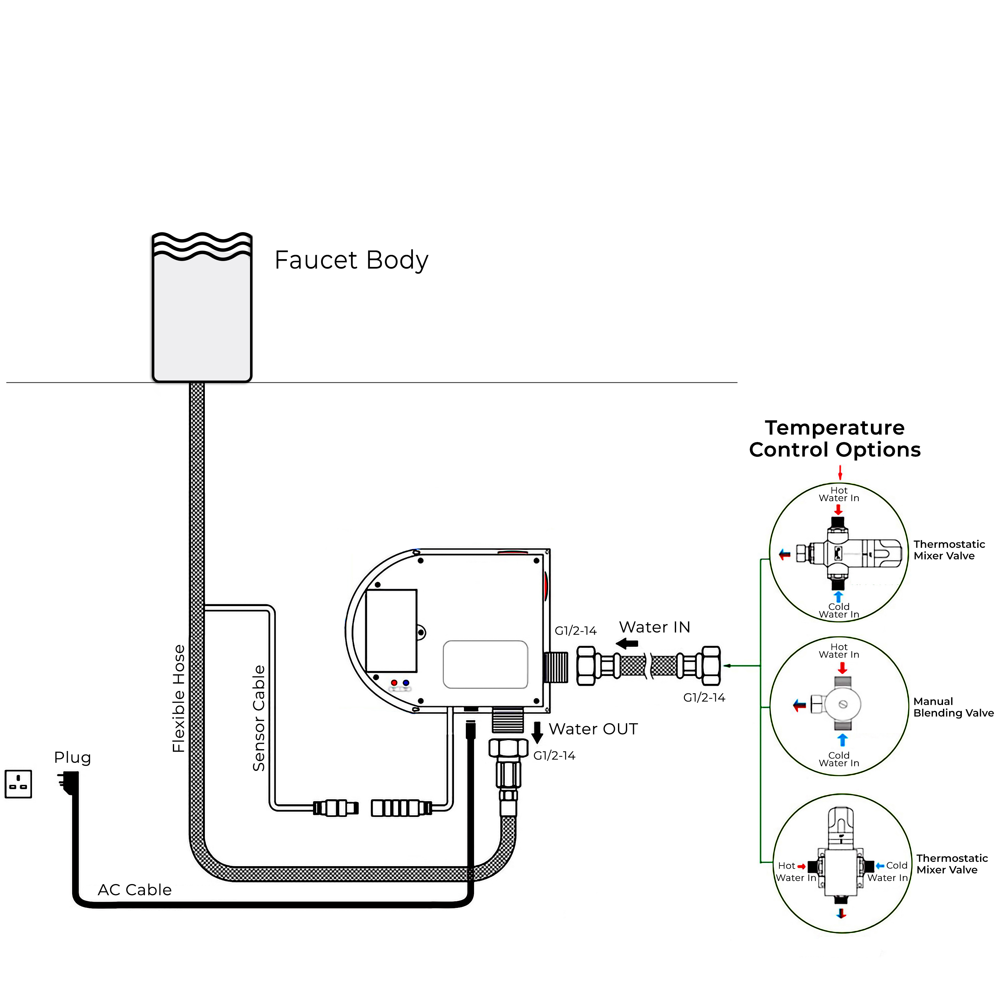
Battery (DC 6V) & AC 220V Control Box
|
|
|
|
Step 3:
|
|
Step 4:
|
|
|
|
|
|
|
|
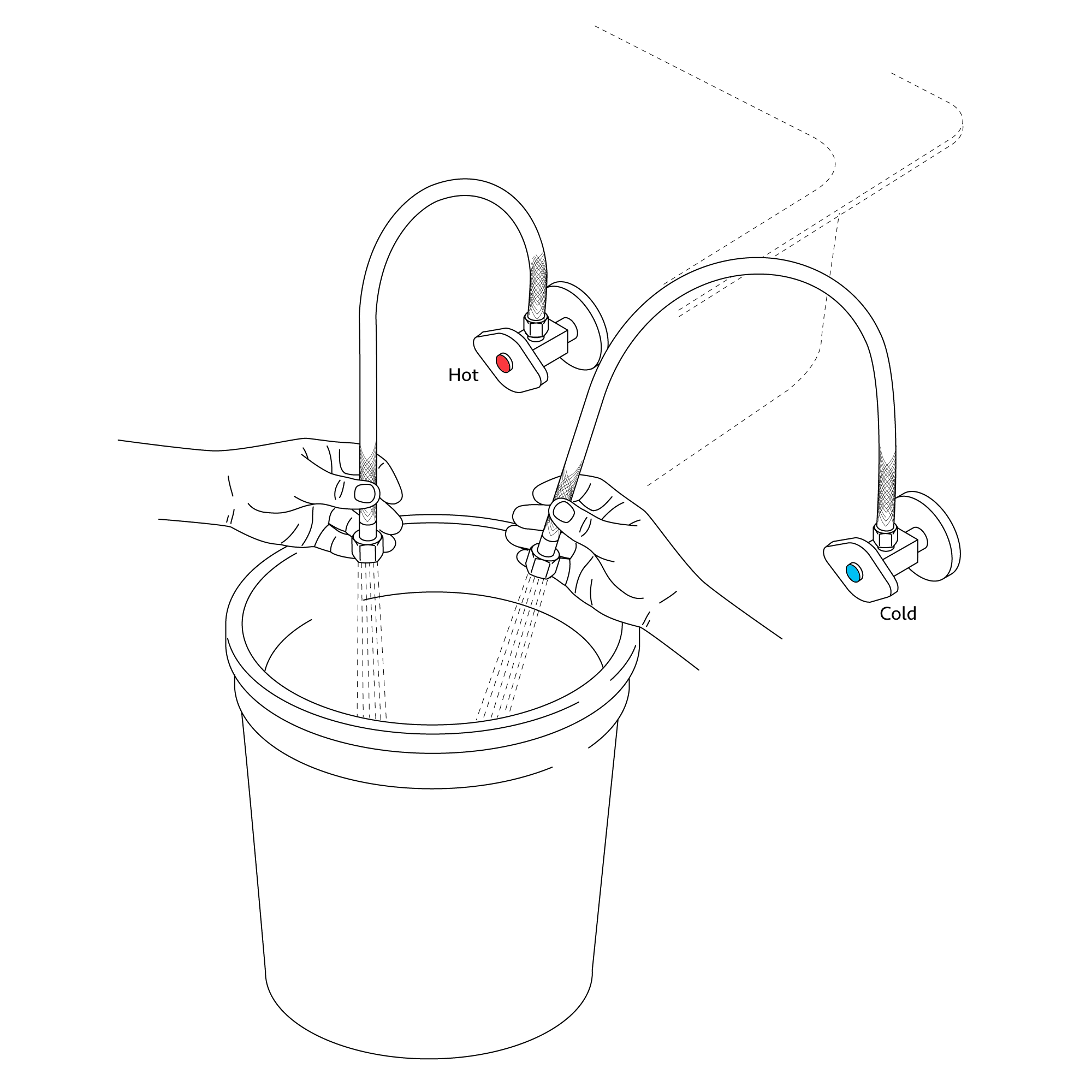
Flush Debris from waterpipes
|
|
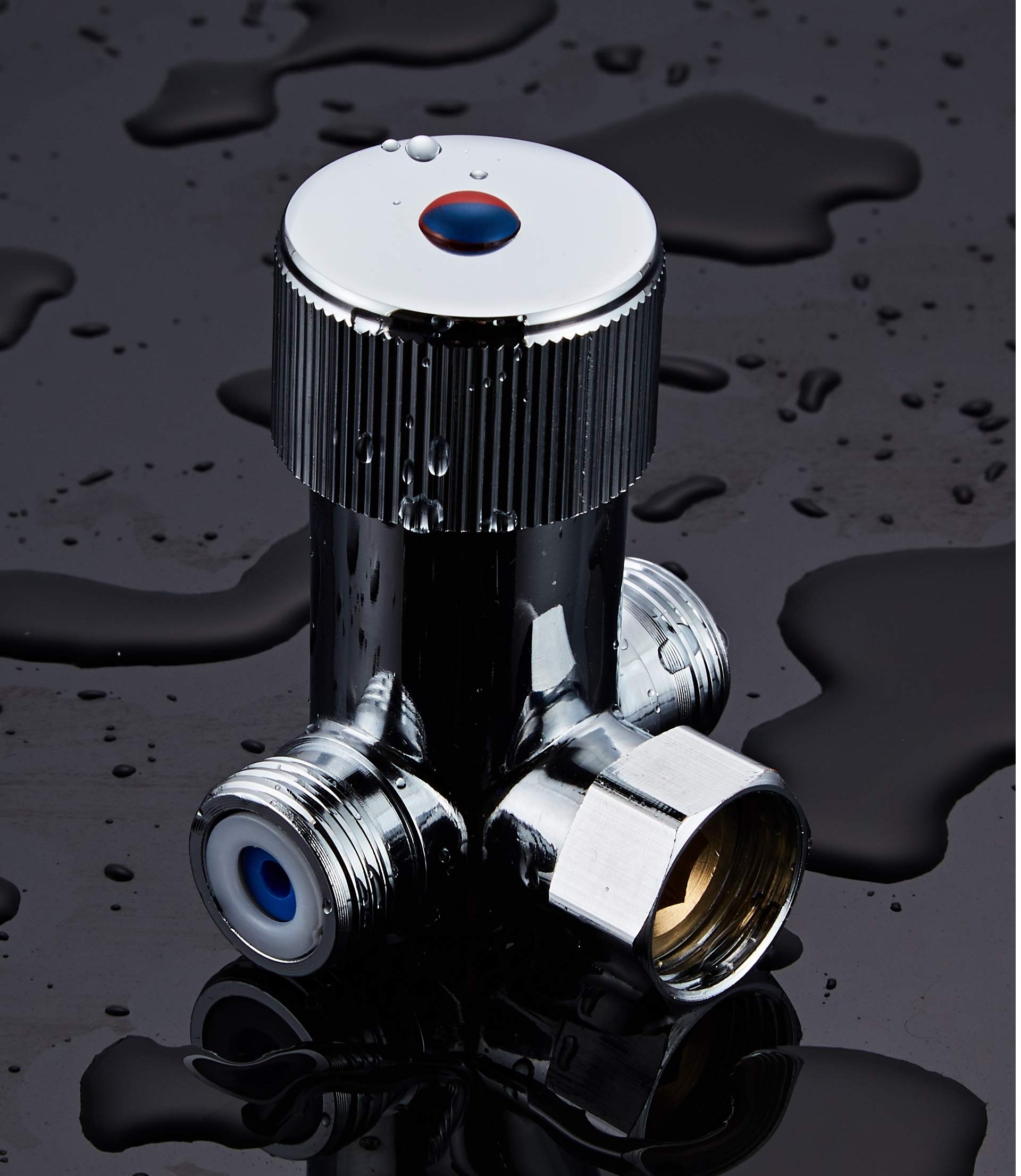
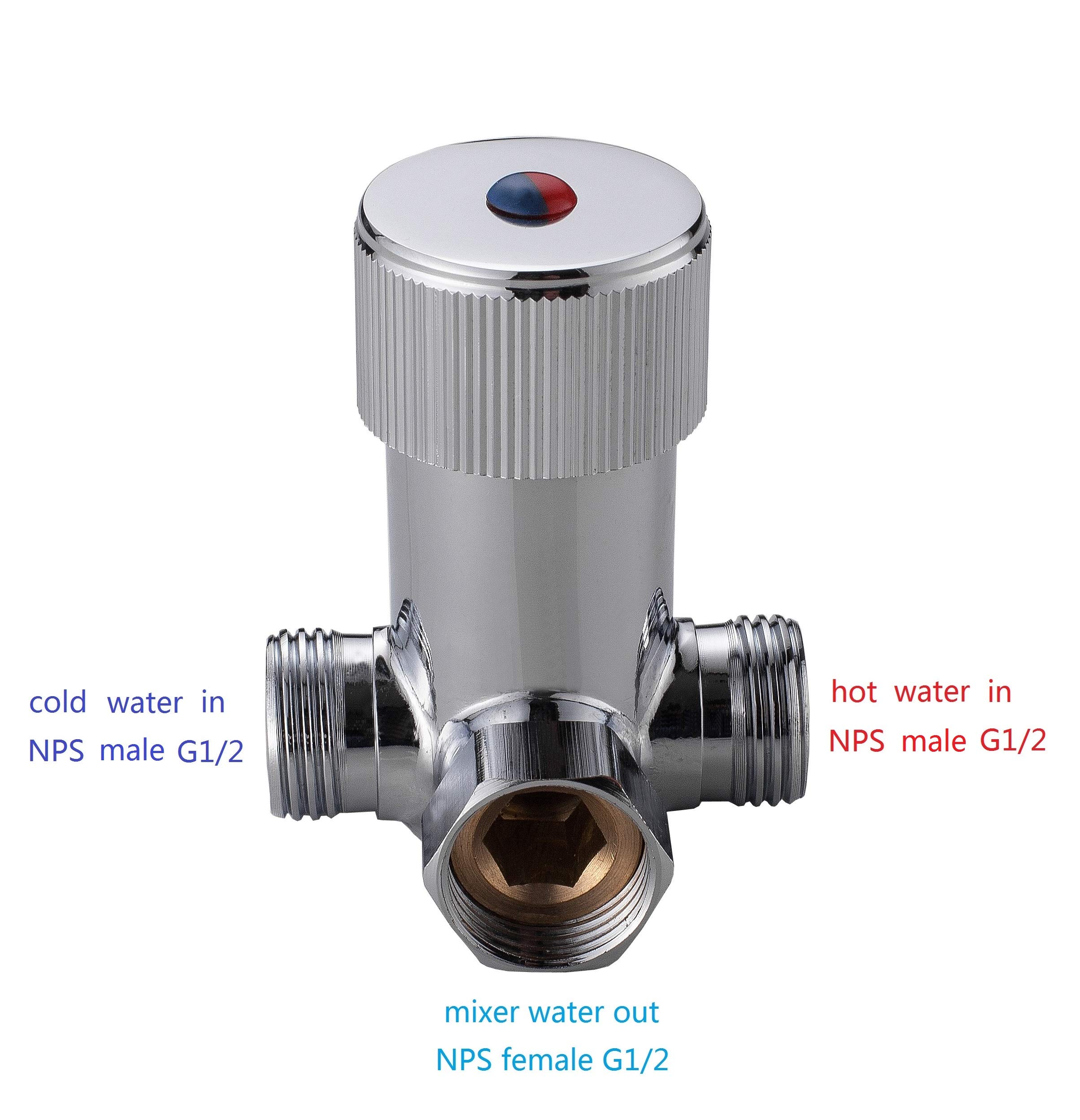
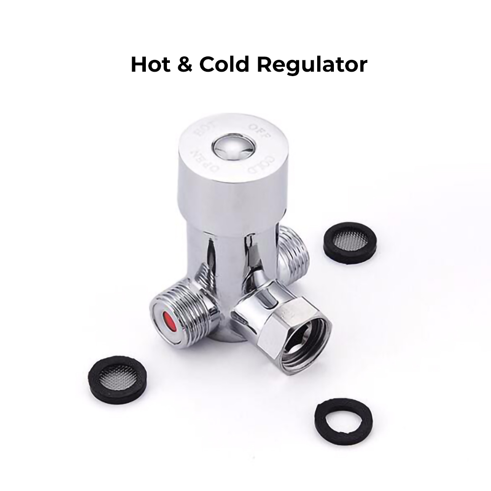
Hot & Cold Regulator
|
|
|
|
|
|
|
|
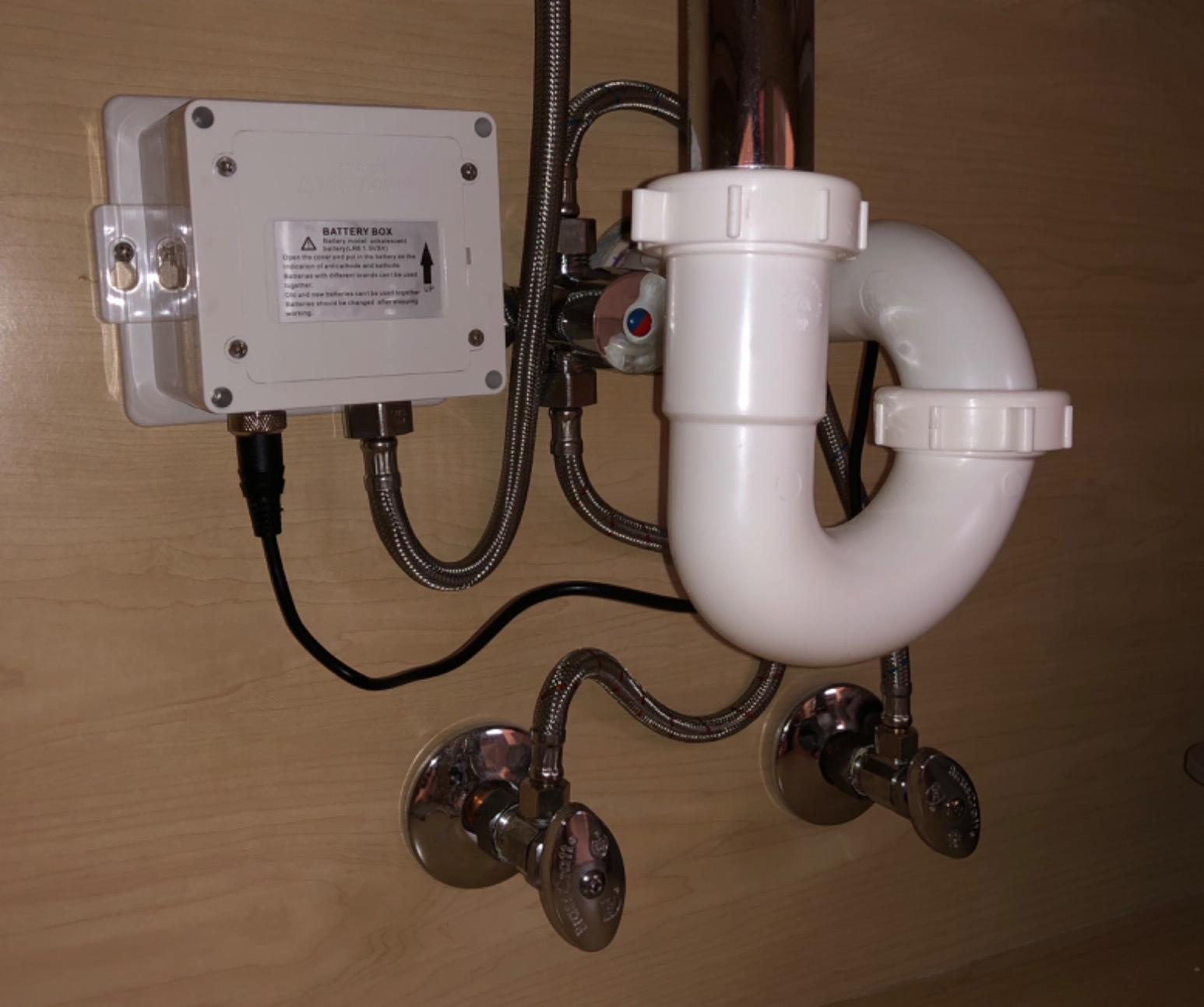
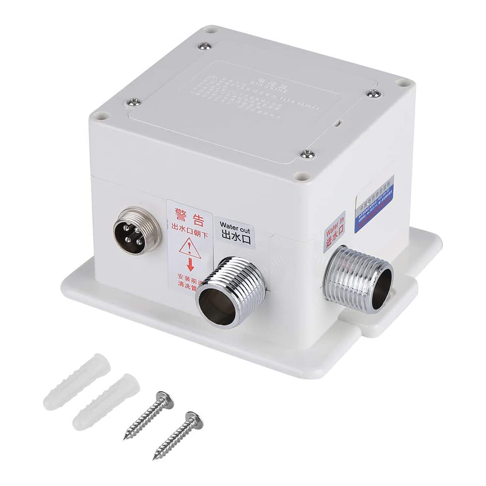
Control Box
|
|
Correct way for Hose
|
|
|

|
|
|
|
|
|
|
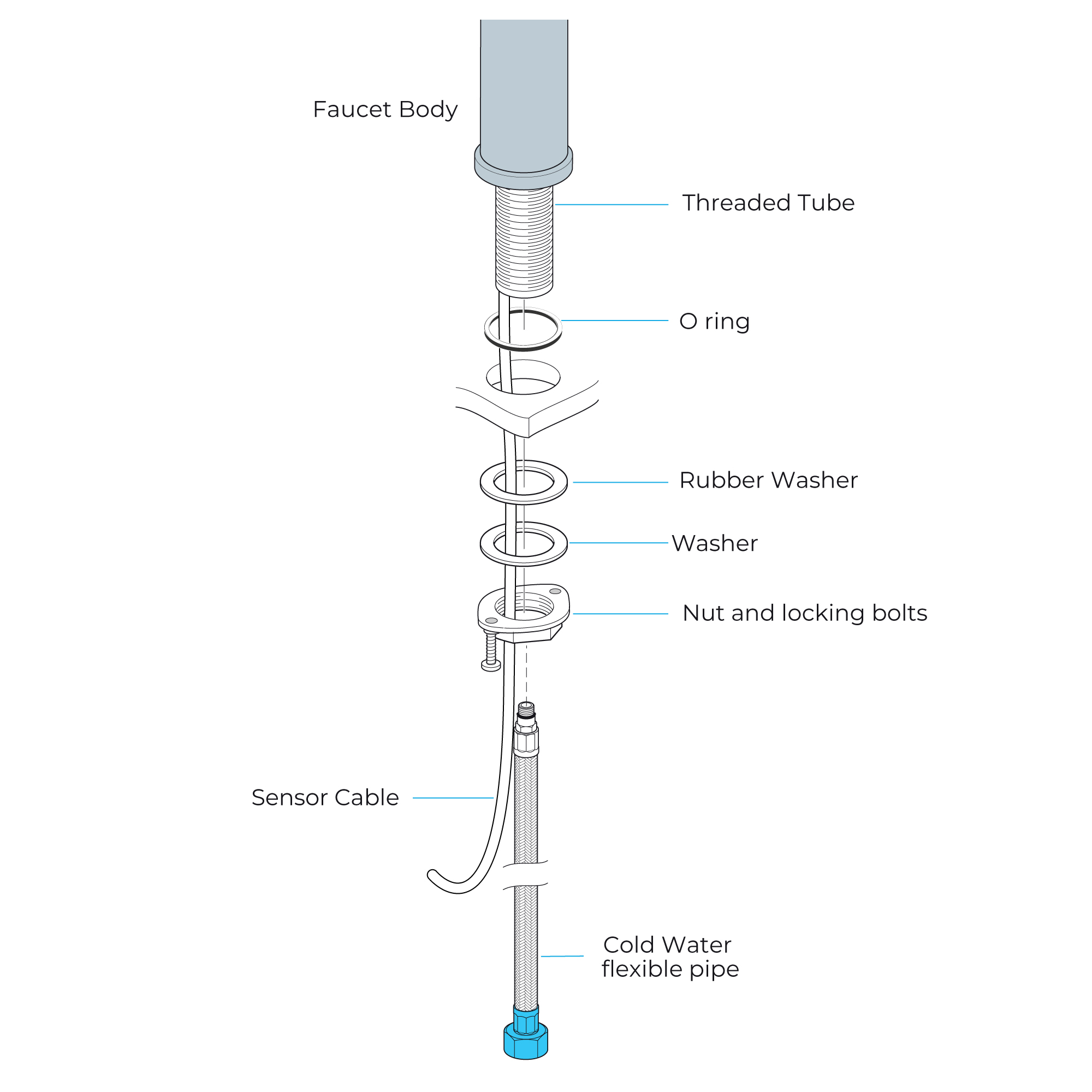
1. Screw the hose on the corresponding screw-hole of the faucet body. Install the o-ring firmly on the bottom groove of the faucet body.
2. Feed the hose, the threaded pipe, and the data cable through the previously drilled hole of the countertop. Install the rubber washer and metal washer over the threaded pipe, and subsequently screw on the mounting nut. Align the position of the faucet and tighten the mounting nut via the screws.
3. Install the control box on the faucet.
4. Attach the battery cable to the control box.
5. Connect the water supply lines. Open the water supply and flush the lines into a bucket for one minute.
Note: This step flushes out debris that may harm internal parts.
6. Attach waterlines to the angle stops. Open the angle stops and inspect for leaks (Do not turn on the faucet).
7. Turn on the faucet for one minute to clear out any leftover debris.
|
|

|
Flexible Connecting Hose
Treat the flexible connection hose from the power box to the spout gently in order not to create sharp turns, kinks, or twists.
Follow the instructions above for safe installation of the flexible connecting hose.
Important: Failure to use these instructions might result in poorer performance and/or damage to the flexible connection hose.
|
|
|
Control Box Installation Instructions
|
Step 1:
|
|
Step 2:
|
|
control box
|
|
|
|
|
|
|
Step 3:
|
|
Step 4:
|
|
|
|
5" size
|
|
|
|
Step 5:
|
|
Step 6:
|
|
|
|
|
|
|
|
Step 7:
|
|
|
|
|
|
|
|
|
|
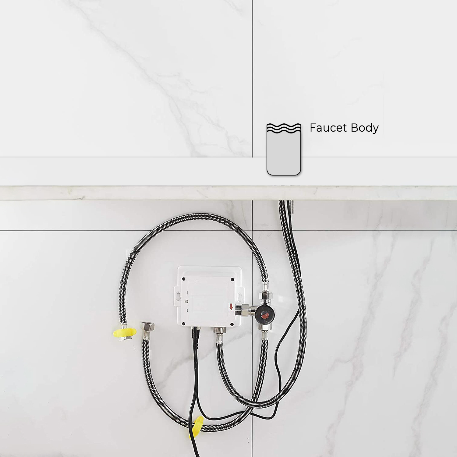
Control Box Installation
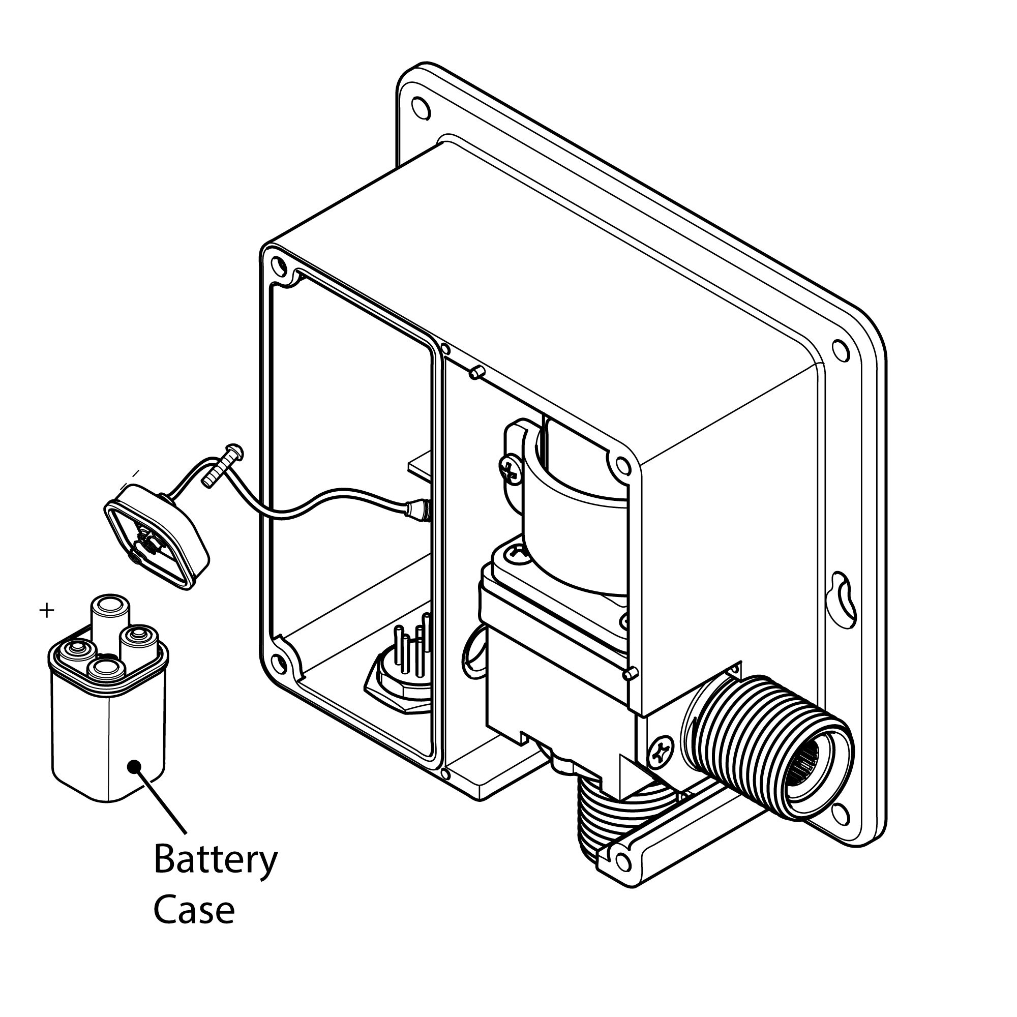
1. Remove the four screws holding the control box cover and remove the cover. Remove the battery box and unscrew the cover of the battery box. Install AA batteries as marked (only alkaline). Replace the battery box cover, align arrows correctly, put the box back in place, and replace the control box cover with the screws.
2. Choose a location under the sink where the control box can attach to the sensor cable, flexible hose, and water line. Drill a minimum 3/4" hole to allow the sensor cable and hose to travel through the sink.
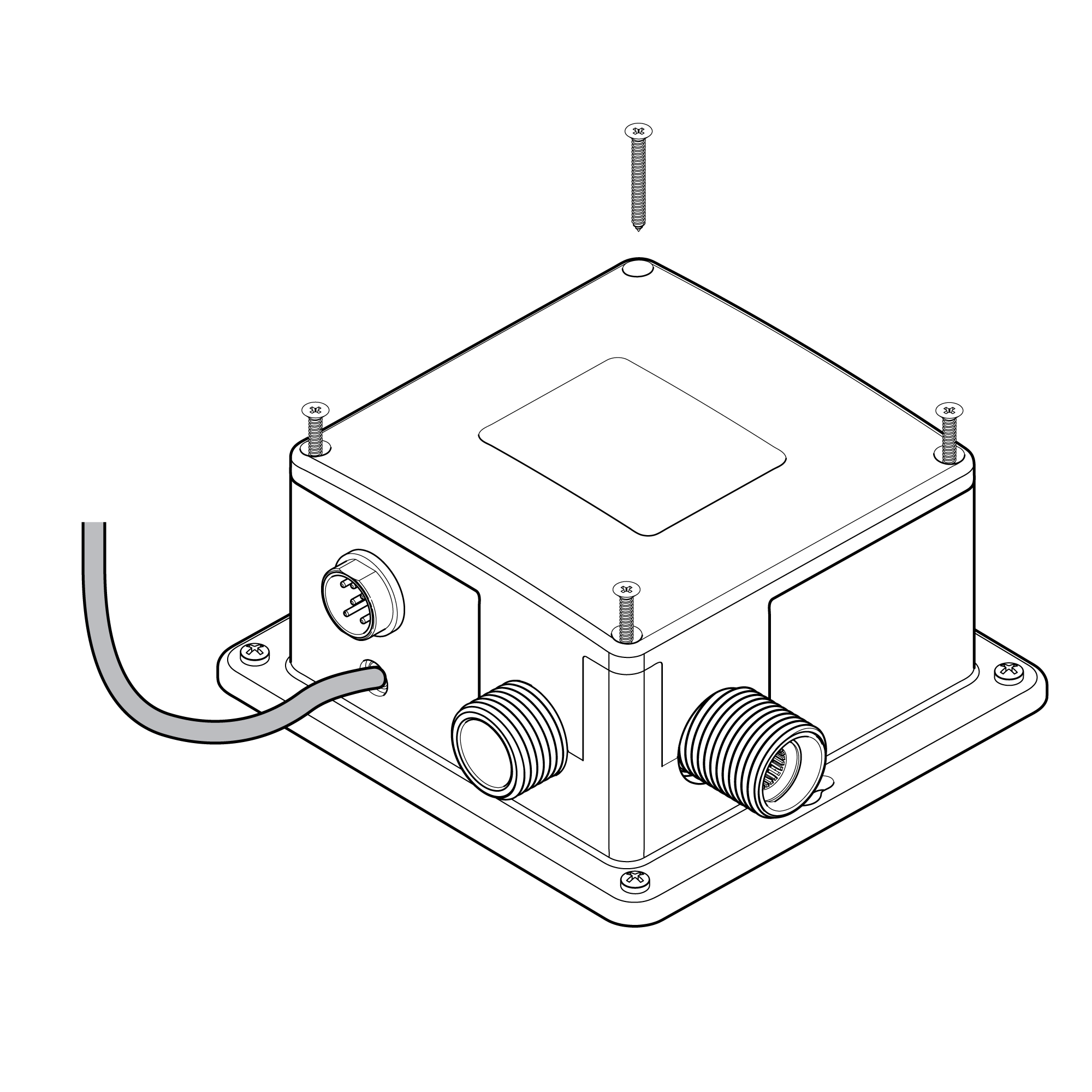
3. Install the control box on the wall as instructed. Drill four 1/8\" (3mm) holes and screw in drywall anchors. Install the control box with the provided screws.
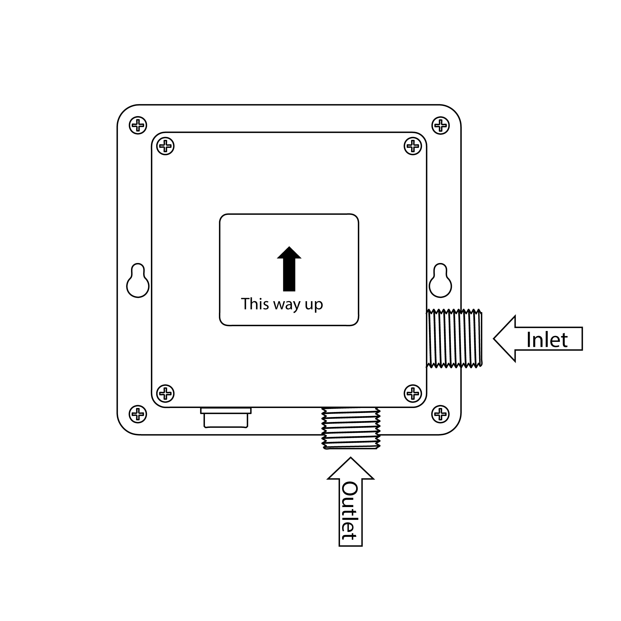
4. Connect the water supply hose to the "Inlet" port of the control box.
5. Tighten the swivel nut on the hose by hand, then with a wrench.
6. Connect the faucet hose to the "Outlet" port of the control box.
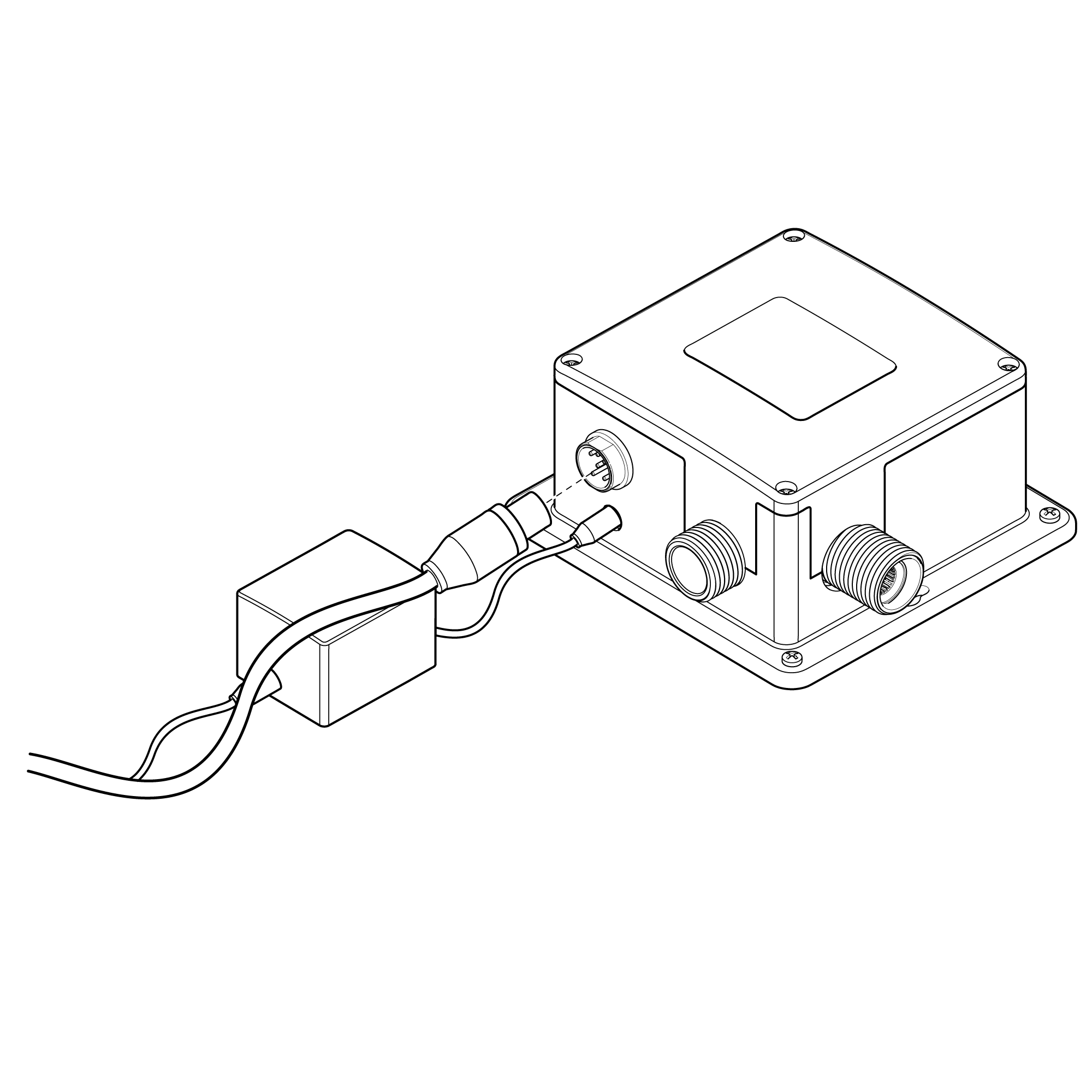
7. Connect the sensor cable to the control box by sliding and tightening the connector by hand.
Note: Turn the water stop valve on before plugging in the sensor, and clean and clear the sink. Let it sit for 60 seconds prior to faucet usage.
|
|
|
|
Inserting Batteries
Your infrared spout has a backup battery pack (no batteries are included). In the event of a power failure, the batteries will be used to supply the power needed to keep the spout working.
Insert batteries before mounting the power supply box to the wall or floor:
1. Remove Power Supply Box Cover – Loosen and remove all four screws in every corner of the power supply box and then pull off the cover.
2. Remove Battery Box – Take out the battery box and the center screw that holds its cover.
3. Insert Batteries – Place 4 AA batteries (not included) into the battery box, with correct orientation.
4. Replace Battery Box – Put back the battery box cover, secure with the center screw, and put back the battery box into the power supply unit.
5. Replace Power Supply Cover – Reinstall the main cover to the power box and secure the four screws tightly.
Electrical Connections
1. Position Power Supply Box - Position the power supply box onto the wall surface below the sink/work surface where it is easily accessible.
Note: Ensure that the power supply box is fitted the correct way up and that the flexible hose will reach from the underside of the spout to the power supply box.
Using suitable fixings for the wall type secure the power supply box to the wall.
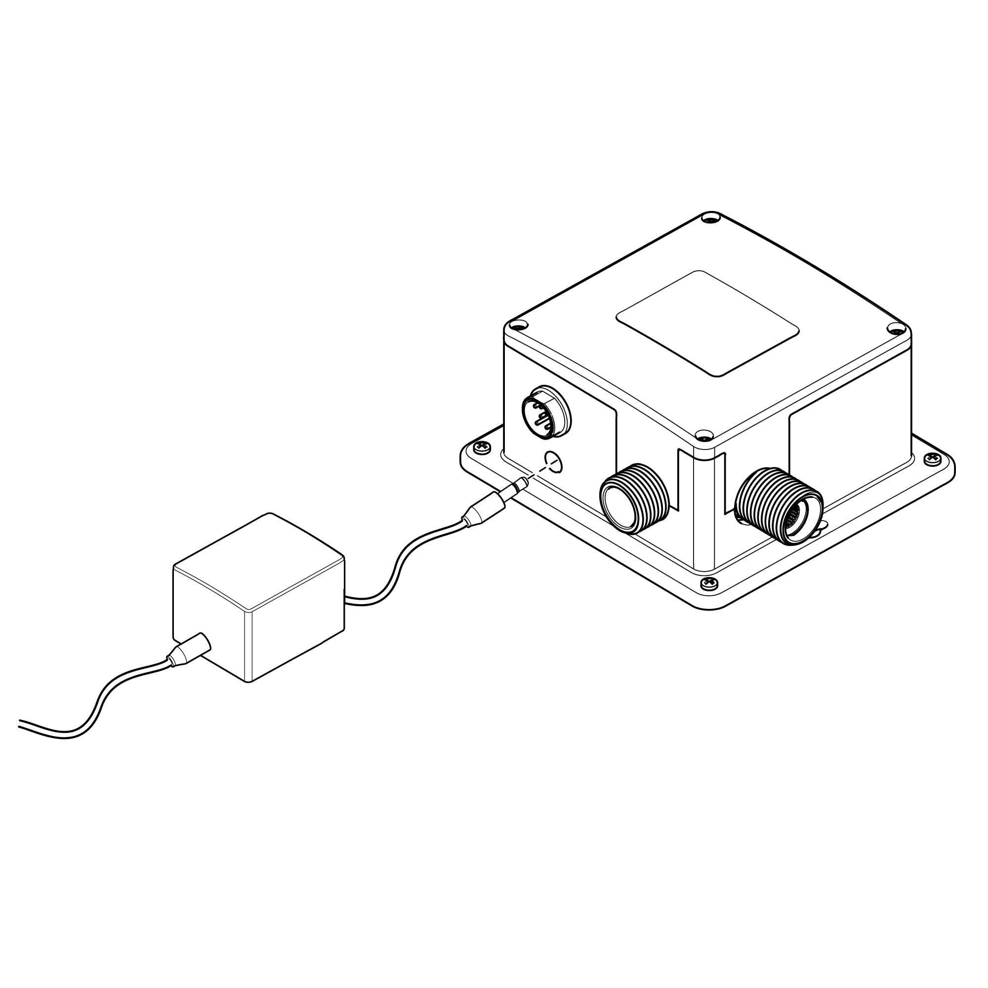
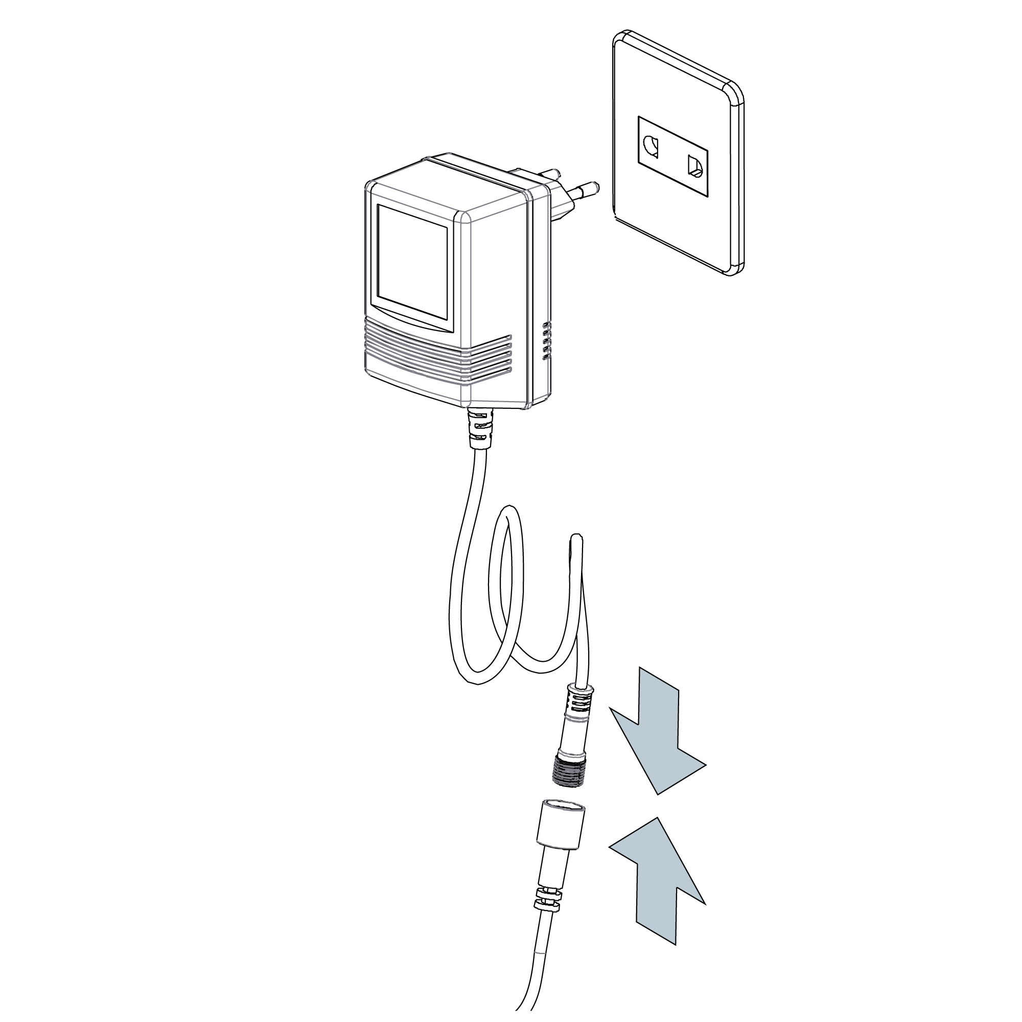
2. Plug-In Power Cable - Plug the power cable into the power supply box.
3. Connect The Sensor Cable - Plug the sensor cable from the spout into the power supply box to activate the infrared senor.
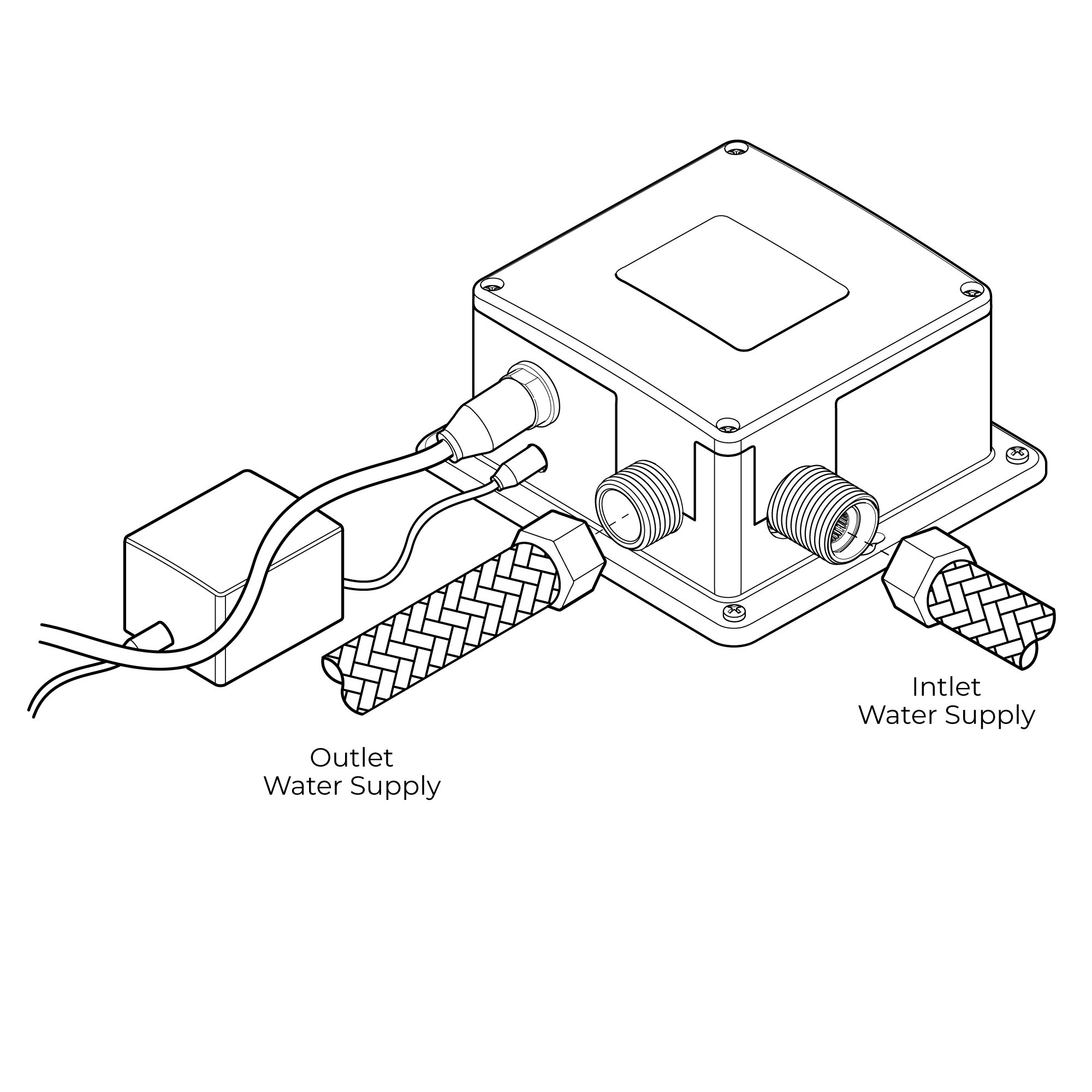
Water Connections
Linking Water Supply - A combination water supply will need to be linked to the power supply box inlet. When connecting, initially flush the pipework out before making the link to clear away any detritus. Then, with the system flushed through, switch off the main supply of water and close any isolating valves.
Inlet Connection - The inlet on the power supply box has a 1/2" BSP male threaded connector. Employ a 1/2" BSP female connector to connect to this inlet, ensuring a sealing washer is used for a watertight seal.
Outlet Connection - The outlet also employs an industry standard 1/2" BSP male threaded connection. Fix the flexible hose to this outlet by ensuring the connection is tightened fully.
Sensor Range
The unit will calibrate its sensor range automatically when powered on within 10 seconds. Do not position any objects or hands around the sensor during this time so it can establish the proper detection distance correctly.
Set Water Flow Time-Out
To avoid perpetual water flow from blockage or abuse, the unit will cut off automatically after 1.5 minutes of continuous sensor activation. To reinstate water flow, simply move your hands away for 2 seconds and reactivate the sensor.
Notes
1. Install only AA 1.5V alkaline batteries..
2. Properly insert the batteries. Don't combine different battery brands, old and new batteries, or use non-alkaline batteries because they might last only 1–2 months.
3. The solenoid valve will carry out a self-test after batteries are installed.
4. It takes 10 seconds for the unit to auto-calibrate the sensor distance once power is being supplied—stay away from using it during that time.
5. If the sensor range becomes excessively short, move any nearby obstruction away for 5–6 minutes to let it be recalibrated.
6. If there is continuous water flow because of a transition from far to near detection, the unit will automatically adjust the sensor range after 5 minutes.
|
|
|
|
|
|
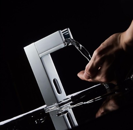
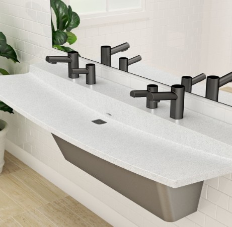
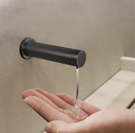
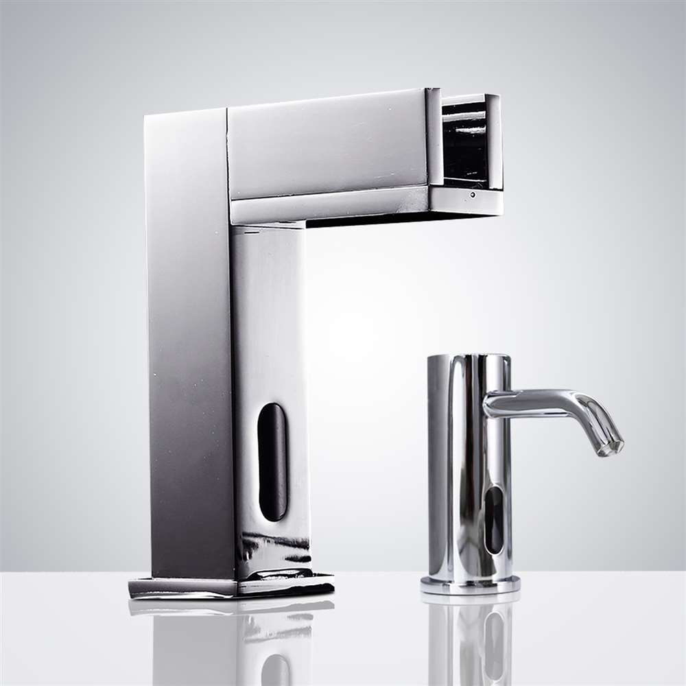
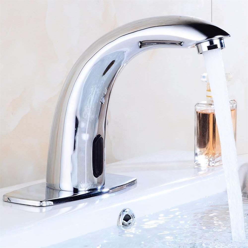
Built To Last Commercial Fontana Smart Infrared Automatic Sensor Faucet
| This Fontana Commercial Infrared touchless motion sensor faucet has an auto-adjusting detection range, is low-maintenance, and incorporates an easy-to-access screen to protect internal components from dirt and mineral deposits. The faucet uses a highly sensitive infrared AI smart-chip sensor, programmed with a 30-second auto shut-off (adjustable). It is ideal for use in commercial settings such as restaurants, hotels, offices, and malls, and provides hands-free use. Its innovative energy-saving technology maximizes battery life. Comes with hoses and installation kit. Dual power sources: AC110V and DC6V (batteries not included). Can be used for residential or commercial installations. Easy to set up with instructions provided.. |
|
|
Features:
- Brand Name: FontanaShowers Commercial Smart Motion Sensor Faucets
- Model Number: FS-544RR
- Type: Commercial Automatic Faucet
- Water Pressure: 0.5-7.0 KGS/cm , 10-125 psi
- Finish: Gold
- Construction: Solid Brass
- Power Supply: AC110V And DC6V
- Batteries Included: Not
- Mounting Type: Deck Mount
- Use: Commercial Use
- Body Material: Brass
- Faucet Mount: Single Hole
- Style: Contemporary
- Flow Rate: 1.3 GPM (gallons-per-minute)
- Ambient Temperature: 1 - 45 °C / 33.8 -113 °F
- Overall Height: 4.72"
- Spout Height: 3.54"
- Spout Length: 6.69"
- Valve Type: Ceramic Valve
- CPU off Warranty: five year
- Usage: Best Fit for High Traffic Commercial Applications for Hotels Restaurants, Office Buildings Malls...
|
|
|
|