Fontana Recessed Ceiling Shower Planning
Plan the Recessed Ceiling Rough-In
Coordinate the ceiling opening, mounting support, supply routing, finished elevation and service access before enclosure.
Installation Hub
Ceiling Mount
Shower Head
Controls
Wall Rough-In
Project Guidance
Frequently Asked Questions
What determines a recessed shower head’s ceiling opening?
Use the cutout and mounting dimensions for the exact SKU—not nominal shower-head dimensions. Coordinate tolerances with the finished-ceiling material. Open Ceiling Detail
When should the finished ceiling elevation be confirmed?
Confirm it before fixing supports or connections because the fixture must align with the final surface, not the unfinished framing.
What should remain accessible above the ceiling?
Preserve access to serviceable connections and components where required by the product documents and applicable codes.
When should the recessed assembly be tested?
Test concealed piping before enclosure and verify alignment, flow, spray coverage and leak-free operation after final installation.
Recessed Ceiling Rain Shower System Rough-In Layout
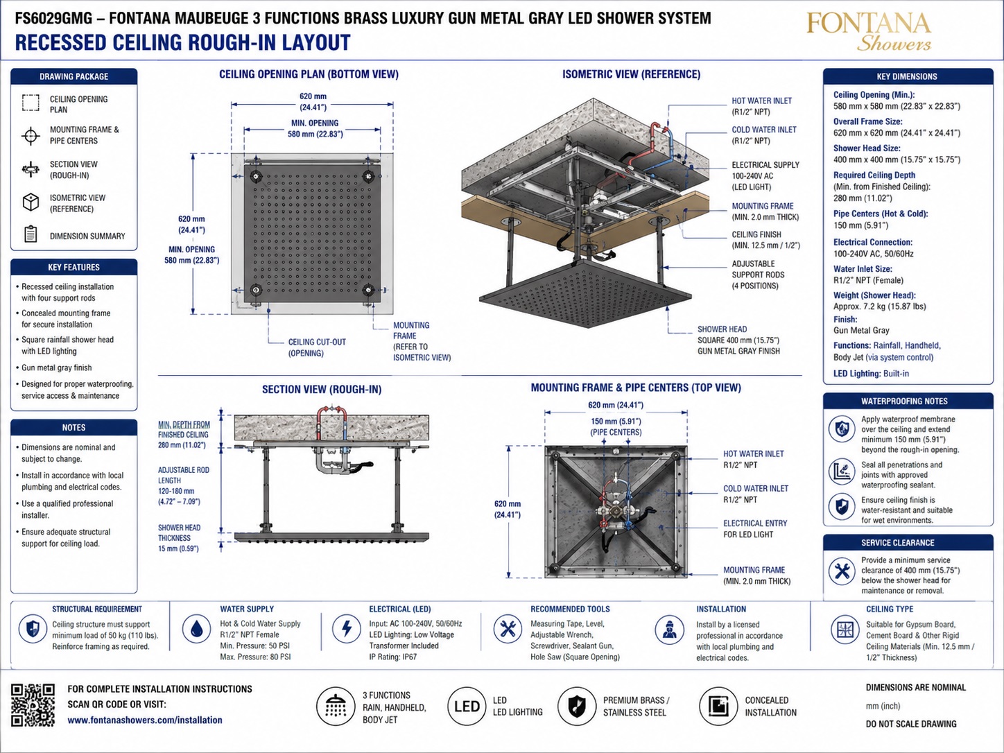
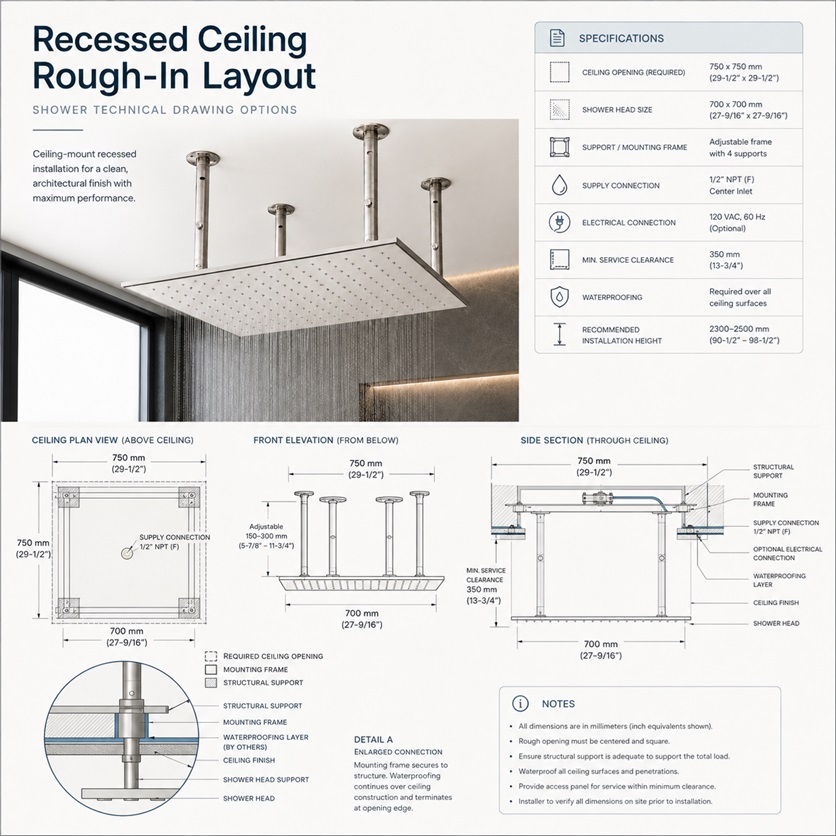
A recessed ceiling rain shower system requires coordinated architectural, plumbing, structural, waterproofing, electrical and service-access information. The rough-in layout should establish the opening, support frame, pipe centers, power provisions and removal clearances before the ceiling is closed.
Essential Recessed-Ceiling Coordination
The drawing should communicate the complete concealed assembly without overwhelming the product image or relying on general installation notes.
- Ceiling opening: Show the rough opening separately from the visible fixture face.
- Mounting frame: Dimension the structural support, attachment points and adjustment range.
- Pipe centers: Locate and identify every water inlet from permanent project references.
- Service access: Provide a measurable working area and a practical fixture-removal route.
- Electrical rough-in: Confirm whether the selected system requires building power, a driver, transformer, receiver or control module.
- Waterproofing: Continue the membrane around the frame, pipe penetrations, fasteners, conduits and access opening.
- Finished alignment: Coordinate fixture centerlines with walls, ceiling joints, lighting and the usable shower area.
- Hydraulic demand: Verify pressure, total flow, valve capacity, branch sizing and simultaneous outlet operation.
- Approved submittal: Base all rough-in dimensions on the selected product rather than a generic shower-head symbol.
- Structural loading: Transfer the fixture load to approved framing rather than ceiling finishes or supply piping.
- Installation tolerance: Record the adjustment range needed for final leveling and finish alignment.
- Technical documentation: Use the linked BIM and architect resources for product-specific dimensions, CAD data and submittals.
Required Ceiling Opening
The reflected ceiling plan and enlarged rough-in drawing should distinguish the required construction opening from the exposed fixture dimensions. Hidden flanges, support frames, removable trim, membrane returns, fasteners and installation tolerances can make these dimensions different.
Opening Dimensions
Show the nominal fixture size, required rough opening, exposed face, mounting-frame footprint, installation tolerance and service-removal clearance as separate dimensions.
Permanent Reference Points
Locate the opening from structural grid lines, finished walls or established room centerlines rather than adjustable decorative ceiling joints alone.
Mounting Frame
Document frame width, length, depth, hangers, anchors, adjustment range and corrosion resistance. Transfer fixture loads to approved structural construction.
Pipe Centers
Dimension every inlet by centerline and identify its function. Multifunction systems may require separate rainfall, waterfall, mist or other supply connections.
Connection Data
Identify pipe coordinates, connection size, thread form, service type, branch diameter, valve relationship, isolation provisions and connection direction.
Hydraulic Review
Check available pressure, total demand, simultaneous outlet use, valve capacity and pipe sizing before finalizing the concealed rough-in.
Coordinate shower heads, hand showers, body sprays and related bath-and-shower supply fittings with ASME A112.18.1/CSA B125.1 and the approved product documentation.
Electrical Rough-In
Where building power is required, show voltage, load, circuit, driver or transformer location, cable route, enclosure, grounding and accessible service space.
Show the framing, substrate, membrane, finish, trim and fixture body. Coordinate powered components with applicable electrical requirements and maintain continuous waterproofing around every penetration.
Technical Rough-In Coordination
Document each drawing element, required information and coordination purpose before fabrication or ceiling closure.
Rough-In Coordination Checklist
Ceiling Opening
Record width, length, tolerance and finished-edge condition to prevent incorrect cuts or visible finish gaps.
Mounting Frame
Show frame size, depth, anchors and hangers so the load transfers to approved construction.
Pipe Centers
Locate each inlet and identify its size and function so the plumbing matches the fixture connection pattern.
Electrical Rough-In
Coordinate power, controls, drivers and cable routes for safe installation, inspection and future service.
Waterproofing
Detail membrane returns, penetrations and seals to protect the concealed ceiling assembly.
Service & Alignment
Provide a working area and removal route while maintaining the intended centerlines, ceiling joints and wall offsets.
Service Clearance and AEC Coordination
Measurable Service Zone
Define access as a dimensioned working space rather than a general note to “provide access.”
Access-Panel Requirements
Show the panel size, opening direction, reach path and clearance around fittings, manifolds, valves and powered components.
Ceiling-Service Conflicts
Keep the access route clear of sprinklers, lighting, diffusers, speakers, ducts, framing and the shower fixture itself.
AEC Case: Initial Conflict
A hotel BIM review found a pipe-to-frame clash, an inaccessible LED driver and an opening based on the visible face rather than the mounting frame.
AEC Case: Coordinated Revision
The team adjusted the fixture, reframed the opening, relocated the driver and dimensioned pipe centers from the finished walls.
Read More: Technical References
Open the supporting BIM, architect, plumbing and electrical reference links.
Technical Reference Links
Coordinated rough-in information protects both installation quality and long-term access.
By documenting the ceiling opening, mounting frame, pipe centers, electrical connections, waterproofing and service clearance before construction, the design team can reduce RFIs, avoid finish damage and preserve maintainability.
|
|
|