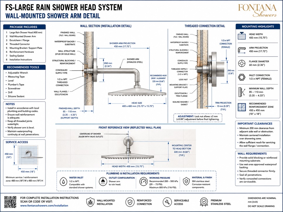
Wall-Mounted Shower Arm Detail for Large Rain Shower Heads
A wall-mounted rain shower arm should be coordinated as an architectural, plumbing and structural assembly. The side-section detail should clearly document projection, wall-flange position, threaded connection, finished-wall depth, supply support, reinforcement and waterproofing so the fixture can be installed accurately and maintained without damaging surrounding finishes. Review the stainless-steel shower-arm collection and architect and specifier technical resources for product-specific dimensions, BIM files, CAD details and submittal information.
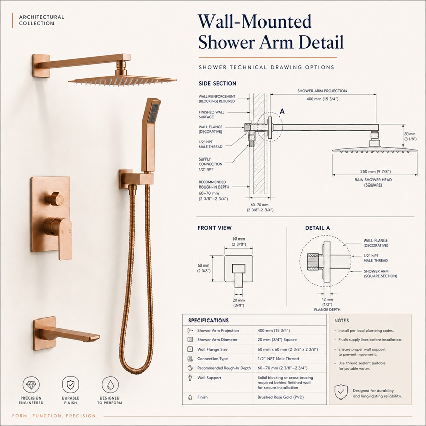
Purpose of the Side-Section Detail
The wall section should show the complete assembly from the concealed supply connection to the installed rain shower head. Dimensions should be based on the approved fixture and measured from finished construction rather than from a generic plumbing symbol.
-
Projection Reference
Measure the shower-arm projection from the finished wall surface to the shower-head connection centerline.
-
Fixture Alignment
Coordinate the final head position with the standing area, controls, body jets, handheld shower, bench, glazing and drain.
-
Finished-Wall Build-Up
Include tile or stone, setting material, waterproofing, backer board and other layers that affect the concealed rough-in depth.
-
Independent Structural Support
Anchor the threaded fitting and support the supply pipe without relying on tile, gypsum board, backer board or the decorative flange.
-
Arm Length and Spray Placement
A short arm can place the rain head too close to the wall, while an unnecessarily long arm increases leverage at the concealed connection.
-
Dimension Limits
State whether the published projection includes threaded engagement, the wall flange, an elbow or the shower-head connector.
-
Product-Specific Selection
Available arm projections vary by model; verify the approved product submittal before fixing the rough-in location.
-
Wall Flange and Finish Plate
Document flange dimensions, finish clearance, sealant position and alignment with tile joints or stone panels. Treat the flange as finish trim unless the selected product is specifically engineered as a structural bracket.
-
Waterproofing Continuity
Maintain the concealed waterproofing membrane around the pipe penetration. Surface sealant at the flange should supplement, not replace, the waterproofing assembly.
-
Threaded Connection
Identify connection size, thread type, orientation and required engagement. Confirm whether the selected model uses G1/2, 1/2-inch NPT or another specified connection.
-
Concealed Fitting and Reinforcement
Secure the shower arm to an anchored drop-ear elbow, wall plate or engineered fitting connected to suitable blocking, framing or masonry support.
-
ASME A112.18.1/CSA B125.1 Coordination
Coordinate shower heads, shower arms and associated supply fittings with the applicable plumbing code, listed components and manufacturer installation requirements.
Finished-Wall Depth & Reinforcement
The section should dimension the complete wall assembly and show how the concealed fitting is reinforced, aligned and protected. Each card below identifies a drawing component, the information to document and its coordination purpose.
Reinforcement Strategy
Show timber blocking, steel channels, mounting plates, masonry anchors or another approved support selected for the fixture weight and arm projection.
Shower-Arm Projection
Dimension from the finished wall face to the shower-head connection so the spray aligns with the usable shower area.
Spray Alignment
Coordinate the head centerline with controls, drainage, benches, glazing and the intended standing position.
Wall Flange
Show flange size, finish clearance, sealant location and the relationship to tile joints or stone panels.
Threaded Connection
Identify connection size, thread standard, orientation and minimum engagement required by the selected product.
Finished-Wall Depth
Dimension substrate, membrane, setting material and finish thickness to establish the correct rough-in position.
Rough-In Tolerance
Record the permitted adjustment range so the flange seats correctly and the threaded connection remains fully engaged.
Structural Anchorage
Show blocking, plates, anchors and attachment methods that transfer fixture loads to approved construction.
Waterproofing Interface
Maintain membrane continuity around the penetration and coordinate compatible sealant at the exposed finish interface.
Supply piping
Show pipe size, routing, concealed elbow and independent supports to limit movement and connection stress.
AEC Coordination Case Example
Existing Condition
A hotel renovation specified a large rain shower head on an extended wall-mounted arm.
Coordination Gap
The original elbow location did not account for backer board, waterproofing, mortar and stone finish thickness.
Installation Risk
Thread engagement was insufficient and the decorative flange could not seat against the finished wall.
Revised Rough-In
The coordinated detail documented the complete wall build-up and repositioned the drop-ear elbow.
Reinforced Support
Continuous blocking was added between studs, eliminating the need for an unapproved extension fitting.
Coordinated Result
The final assembly provided full engagement, a flush flange and stable support for the projected shower head.
Accessibility Coordination
Installation Coordination Outcomes
A coordinated wall-mounted shower-arm detail supports accurate rough-in, secure anchorage and reliable alignment.
Final dimensions, thread type, reinforcement, waterproofing and accessibility provisions should always be verified against the approved product submittal and project requirements.
|
|
|